
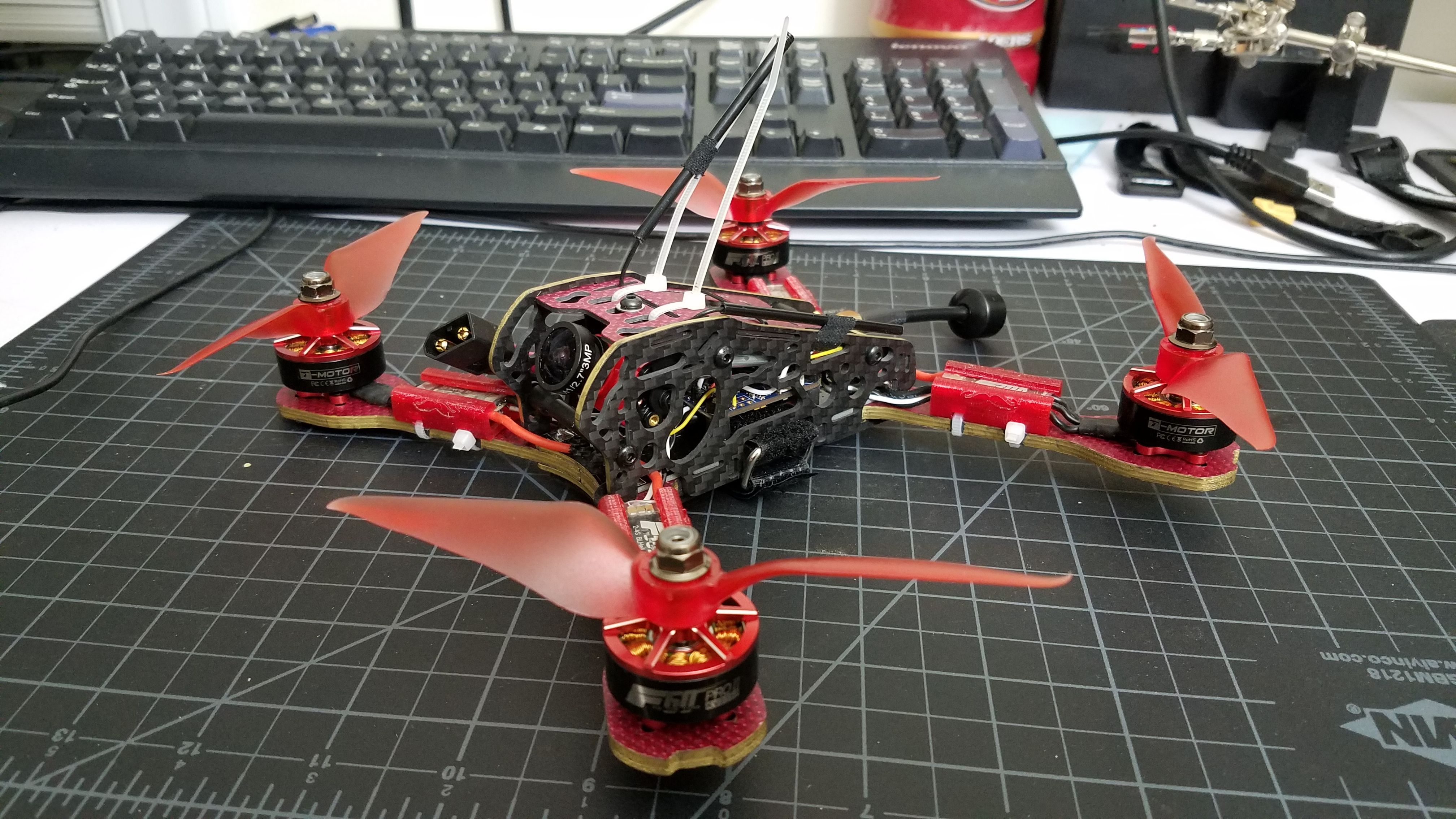
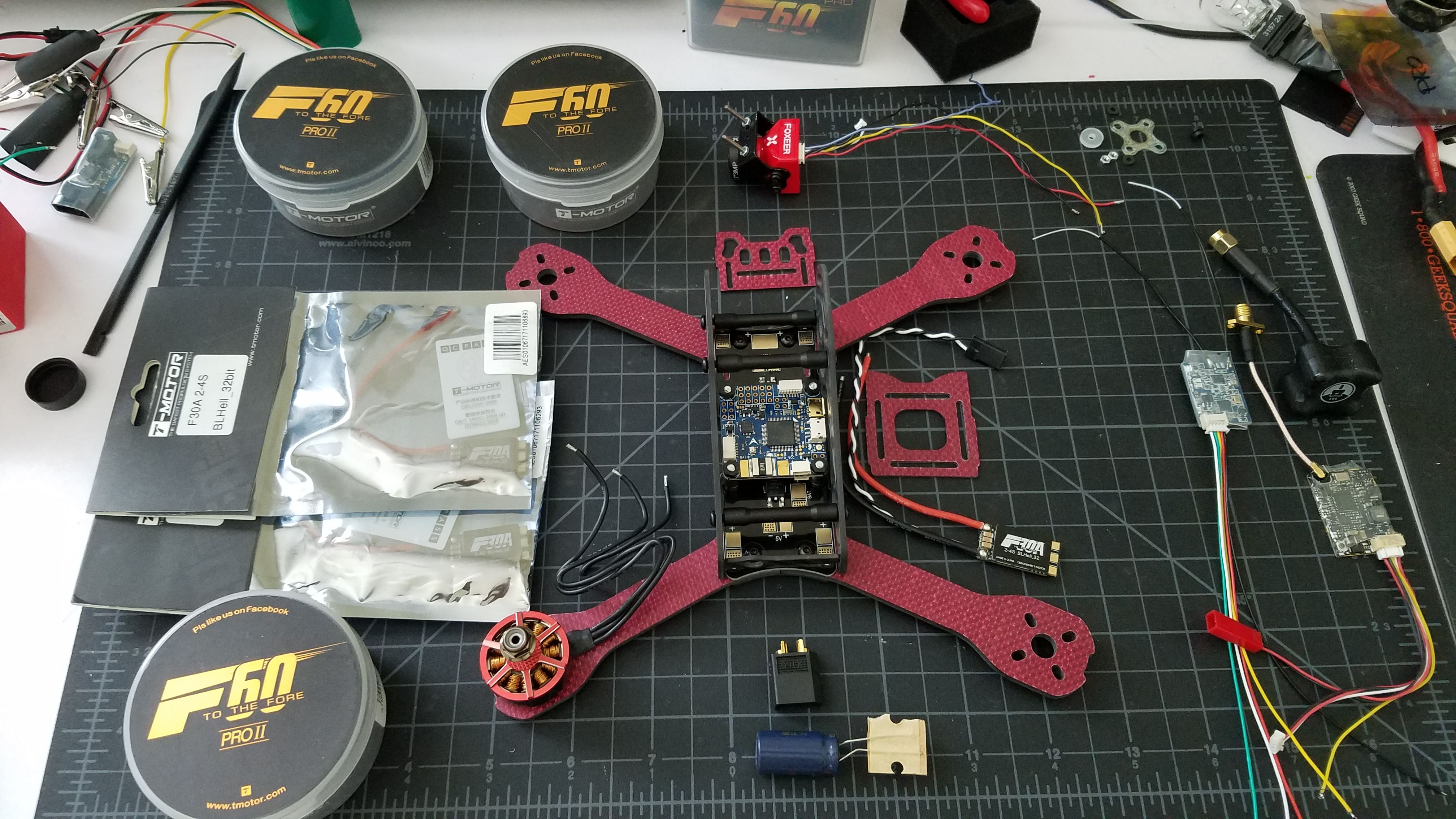
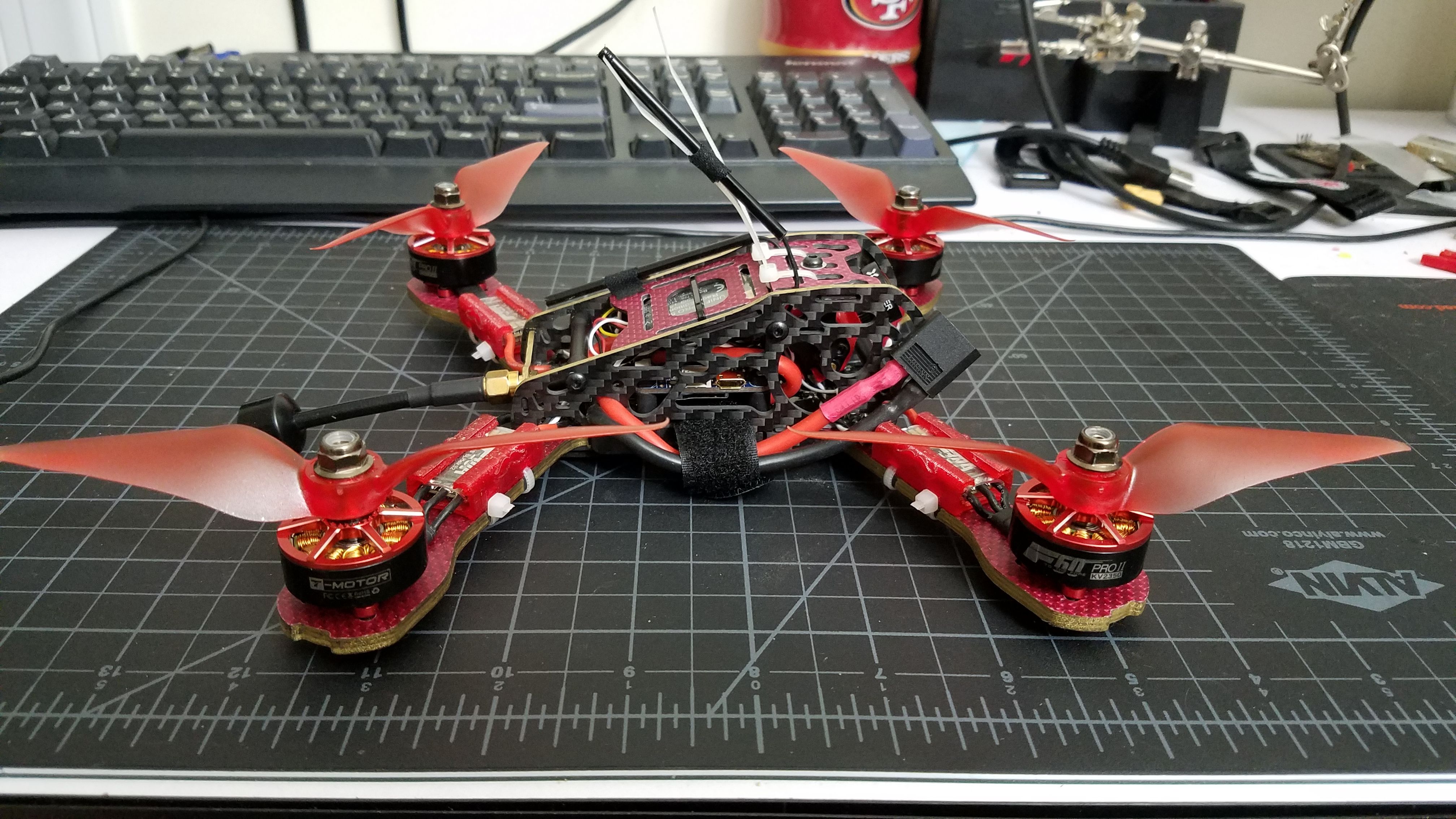
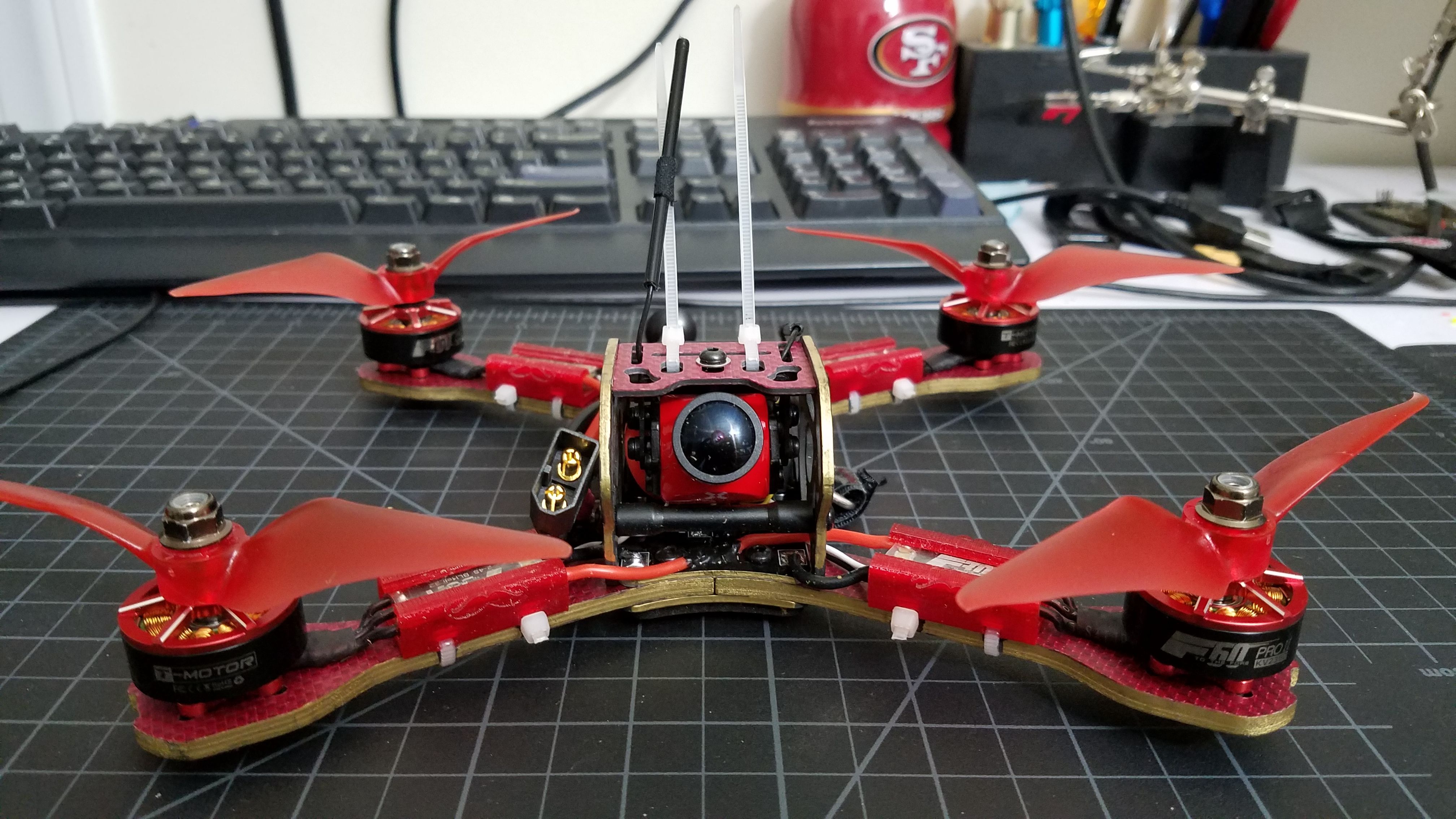
Mark III - what started out as spare parts became the next build in my collection. The majority of this build were spare parts I had sitting around for my other squirlly birds: Frame, FC, ESC's, receiver, VTX, antenna. I was only short the camera, and motors.
Having already been a fan of the Foxeer monster series I immediately wanted to try out the monster mini when it was released.
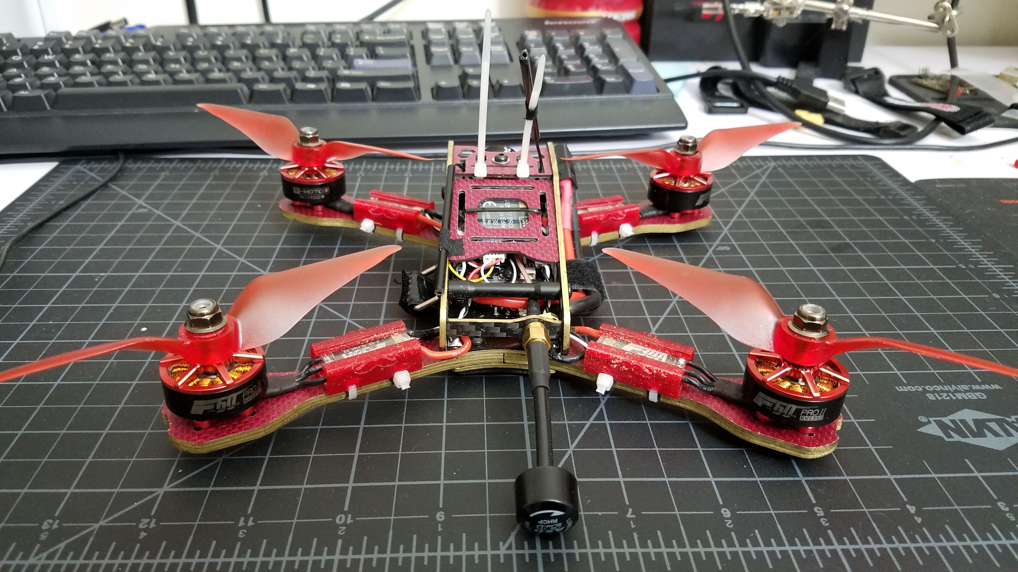
Then reflecting on my experience with all my motors (Cobra, Luminier, T-Motor, Emax) I decided to pull the trigger on some F60 Pro V2 2350s. Mark 3 was born.
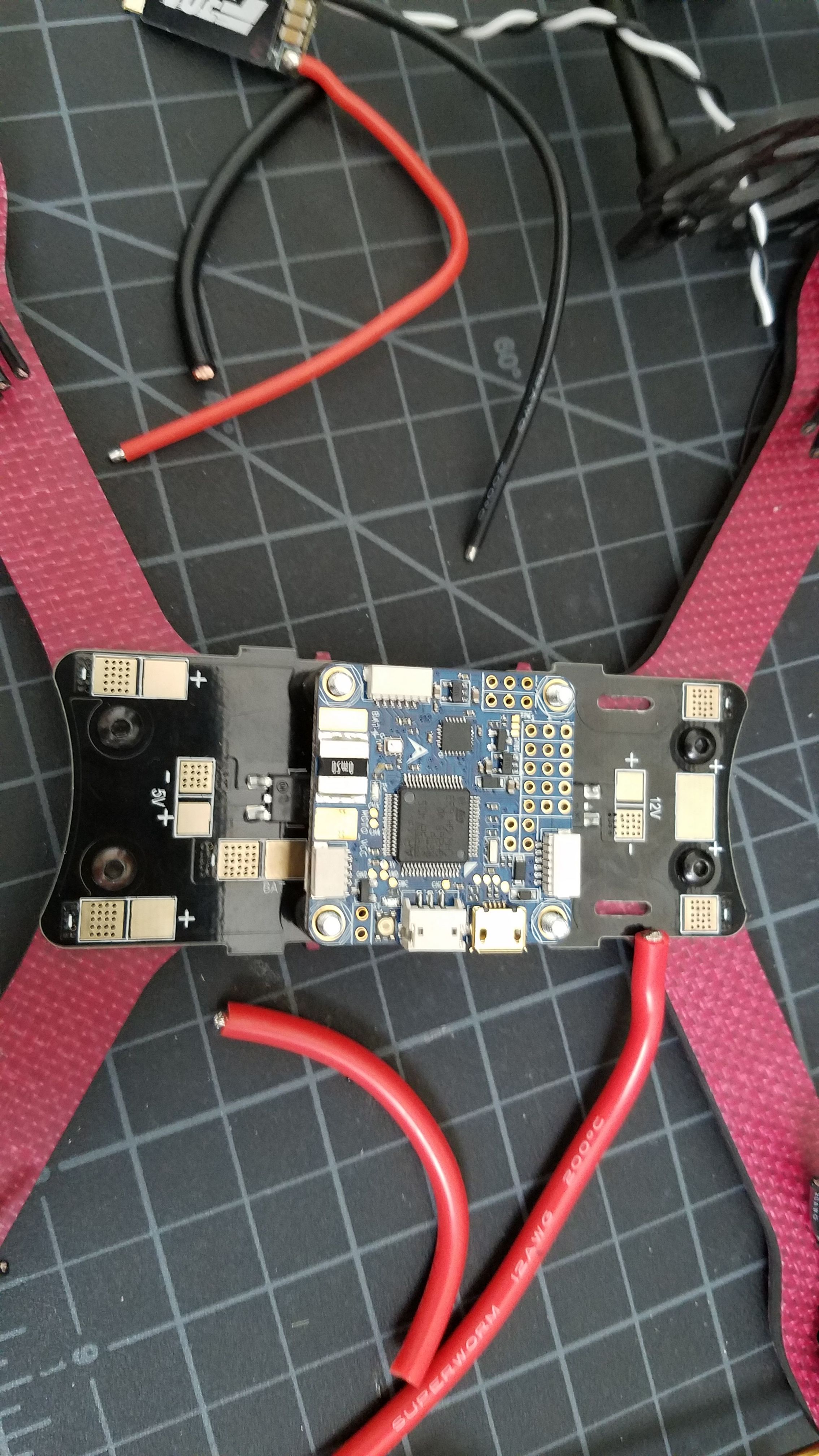
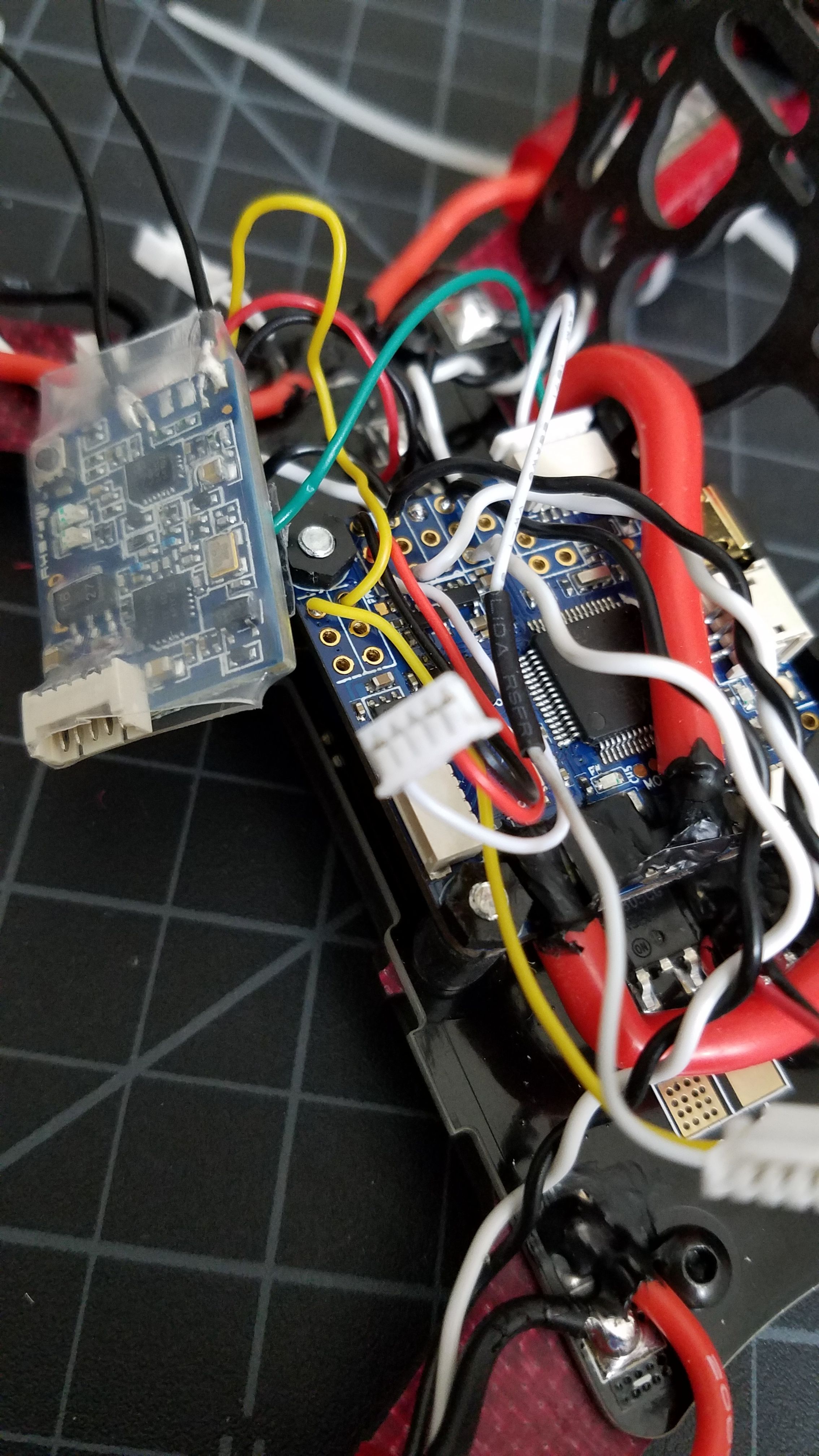
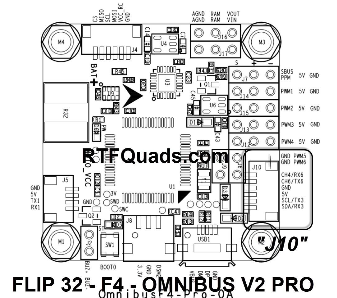
I wanted to take advantage of the current sensor in the Omnibus F4 pro, however I faced a small dilemma when it came to running the power lines.
The built in PDB the armadillo comes with contained two locations to tap the lipo leads into, towards the back and slightly front center of the frame.
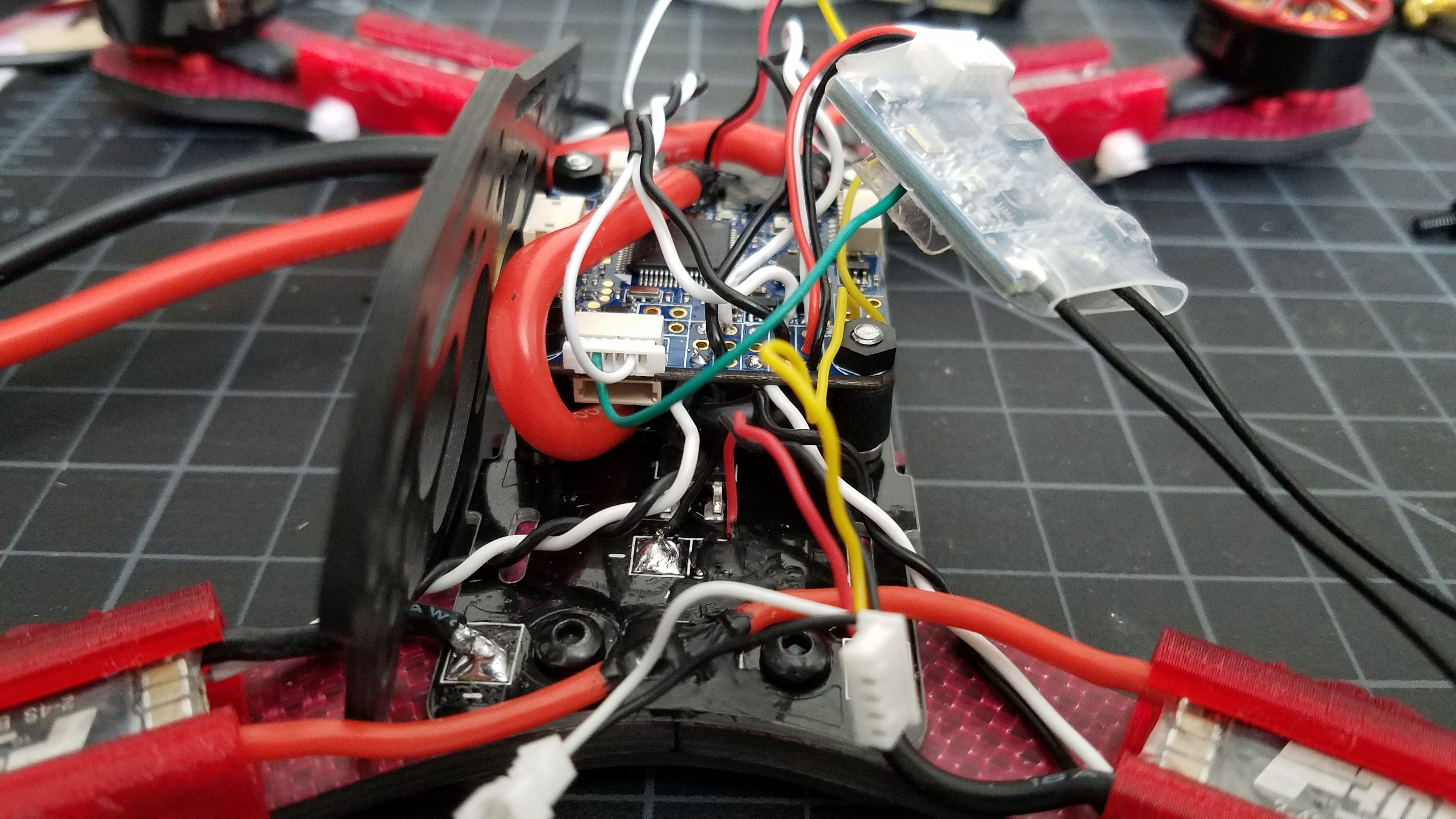
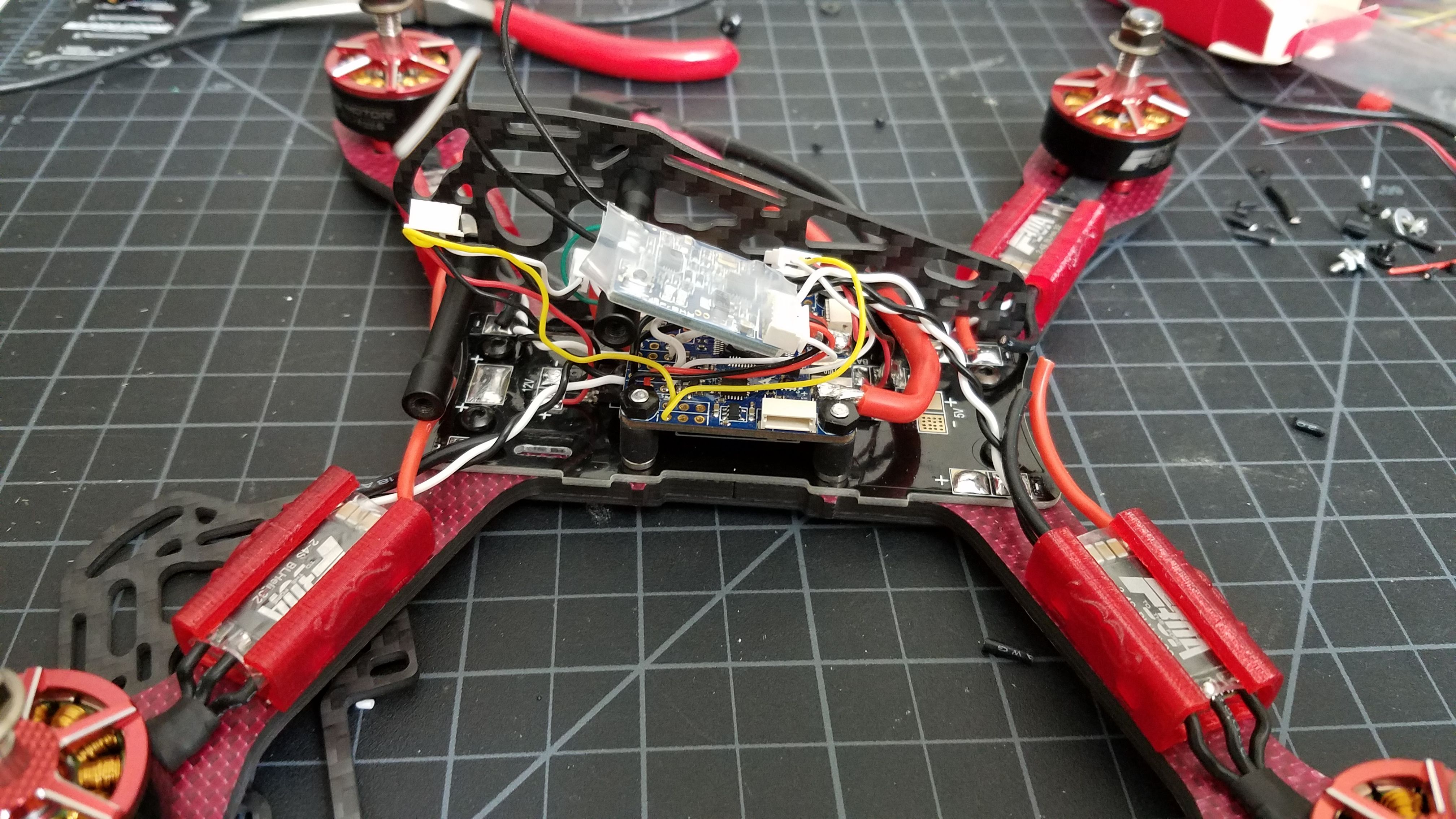
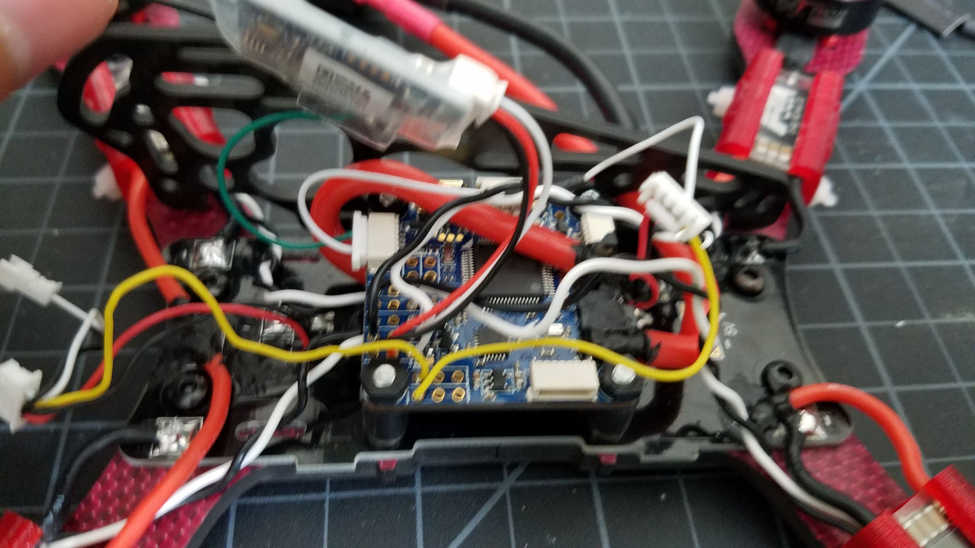
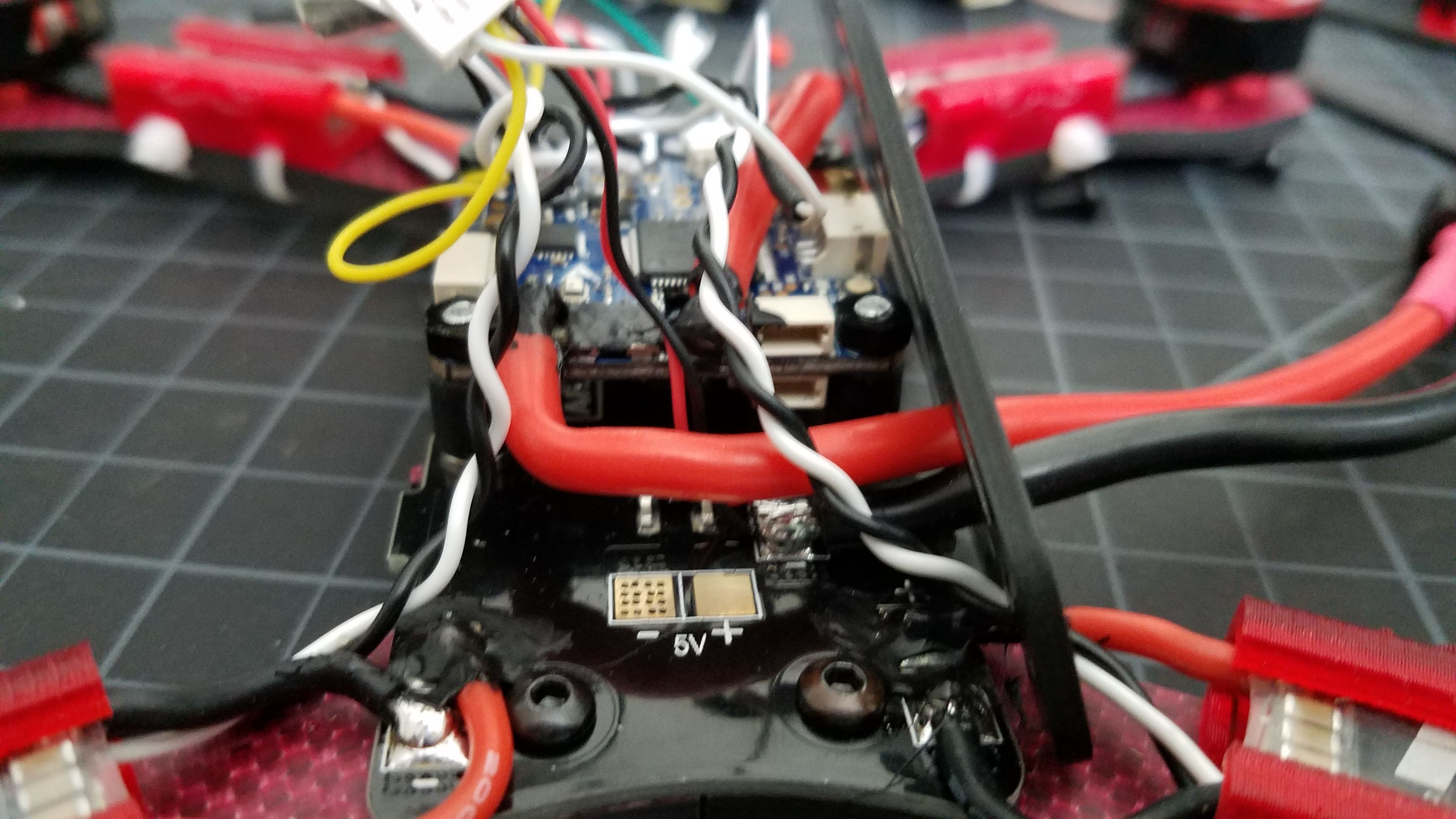
Unless I rotated the FC to be a different orientation, the current sensor pads would be located towards the back. The current sensor requires for the positive lead to come directly from the lipo, and the negative could be direct or connect to the PDB, as long as it completed the circuit. Having already built an armadillo, I was wanting the location of the lipo leads to be identical on the frame, which means having the lipo leads exiting from the right. After toying with how wires would run, I decided to run the positive lipo lead directly to the FC and out the right, then have the negative connect to the back PDB pads. A wire would then run from the FC postitive pad to the center PDB pads, however so that I don't clutter things up towards the back of the frame this required for me to go over the FC and do a 360 bend to under the FC. The negative pad on the FC is located on the bottom, so I ran a wire to the center pad as well.
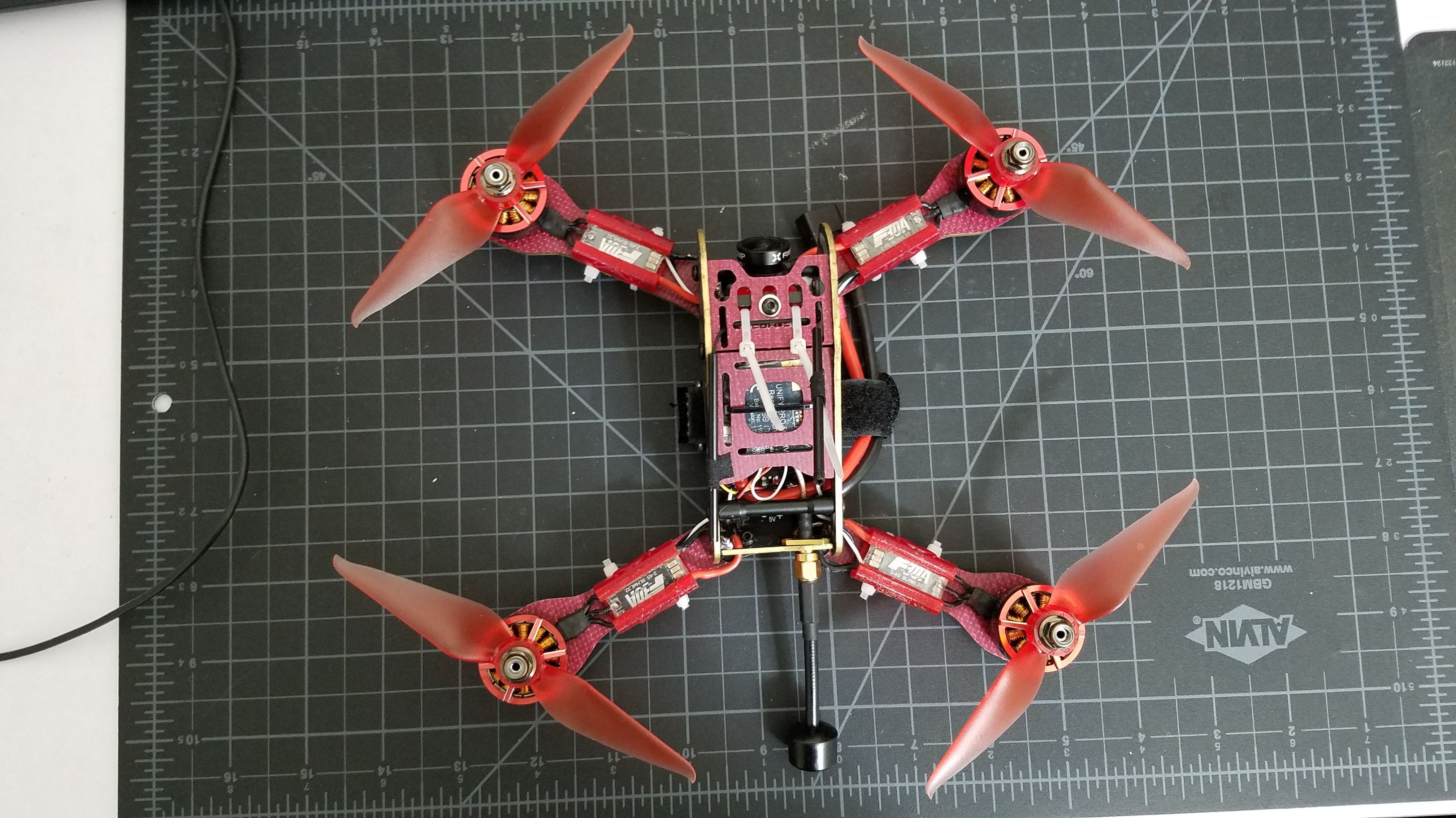
With the camera being a mini and the Armadillo having its own type of camera mount, I faced another issue. I could have either used the armadillo camera mount and modify it so the mini would fit (as i did with the Eagle on my BlueSteel build), or use the foxeer mount extender and find a way to attach it to the frame. In the event I swapped cameras and needed the original frame camera mount, I went with the latter. The bottom of the armadillo is it's PDB so drilling any holes and attaching it there was out of the question. I attached the camera mount extender so the mounting holes were over the camera so the camera is "hanging". I used two zip ties to attach the mount to the top plate of the frame, then used an m2 screw in the center hole to keep the camera from sliding side to slide.
Since I have the TBS Race I took advantage of using smart audio, but in order to be able to send and receive telemetry to and from my Taranis I needed to perform the s.port work around for the XSR since on the Omnibus the ONLY inverted channel is used by the SBUS. This involved having to solder a wire under the XSR onto a small diode(?). This wire was then routed to a JST connection to utilize UART3 on the fc. Since I needed to invoke the use of a JST connection, I then ran another wire between UART6 to the TBS Race Audio Port.
This was yet another fun build. For now I started flying as an acro quad, but I would like to see how it does in racing. I plan to setup two rate profiles specifically for racing and acro. These motors are AWESOME! TMotor has done it again, and being a fan of the first series, I definetly wasn't let down. On my other builds I chamfered the arm edges, however due to the lifetime warranty with Armattan I decided to forego that procedure. The built in current sensor on the Omnibus will allow me to get more lipo data using my custom OpenTx lipo log. The armadillo is so nimble and light weight, the copoments used work so well together reponse is immediate. With the tilted back of the armadillo this allows me to mount my Runcam HD without taking away from the aerodynamics. Great build, Great products!
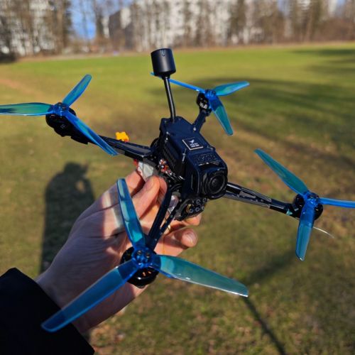
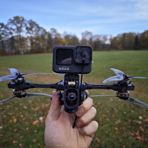
Photos
Part List
Frame |
Armadillo
(6 builds)
Armattanquads.com
|
$85.00 |
Flight Controller |
Airbot Omnibus F4 Pro V3 30x30 Flight Controller w/ Baro, Current Sensor, OSD and SmartAudio
(61 builds)
Racedayquads.com
|
$26.59 |
ESCs |
4 x Tiger Motor F30A 2-4S ESC BLHeli_32
(8 builds)
Getfpv.com
|
$63.96 |
Motors |
Best Drone Motors for - RaceDayQuads
(26 builds)
Racedayquads.com
|
$24.89 |
FPV Camera |
Foxeer Monster Mini Pro FPV Camera (1.8mm) (Red) | Heli-Nation
Heli-nation.com
|
$25.90 |
FPV Transmitter |
Team BlackSheep TBS UNIFY PRO 5G8 HV - RACE V3 (SMA) Video Transmitter - Heli-Nation
(555 builds)
Heli-nation.com
|
$24.99 |
Antenna |
Lumenier AXII 5.8GHz Antenna (RHCP) (2pcs)
(199 builds)
Getfpv.com
|
$29.99 |
Receiver |
FrSky XSR
(481 builds)
Pirofliprc.com
|
$14.99 |
Goggles |
FatShark Dominator V3 FPV Goggles
(63 builds)
Helidirect.com
|
$349.00 |
Video Receiver |
FatShark Dominator 5.8GHz Module
Hobbyking.com
|
$15.00 |
Guides & Reviews
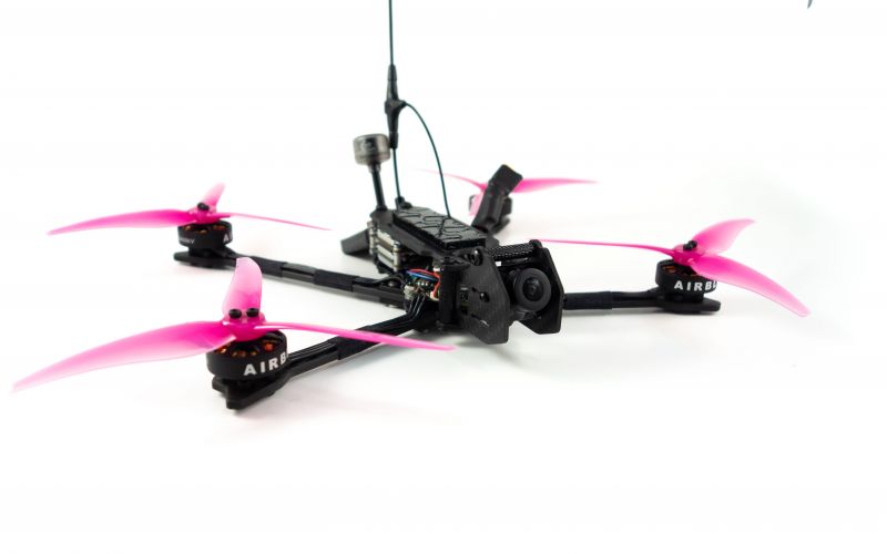
AirbladeUAV has done it again and this time they've brought long range to the 5" class! Based on the popular Transformer Mini, the new Transformer 5" Ultralight adopts a lot of the same design philosophies with larger props and more payload capacity. It can fly upwards of 20 minutes on a 4 cell Li-Ion battery pack and in ideal conditions it's got a range of over 4 to 5 miles. In this guide I'll walk..
Read more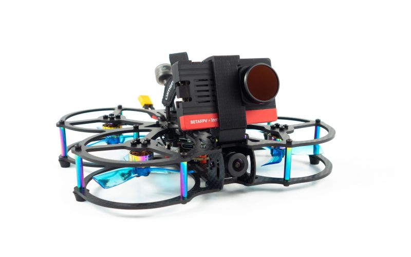
With the release of the DJI FPV Drone cinematic FPV has become a lot more accessible, but you certainly don't want to crash a $750 drone! The QAV-CINE Freybott is a compact, lightweight cinematic FPV drone that can take a hit and keep going. It's a lot safer to fly indoors and around people. With a naked GoPro or the SMO 4k you can capture some great stabilized footage. In this guide I'll show you..
Read more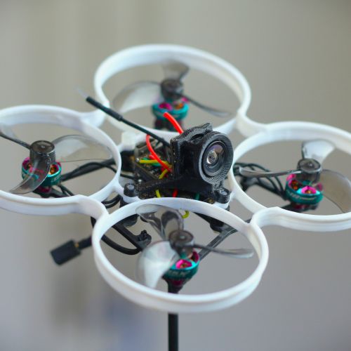
So I really dig the red trim on so many parts, and the subtle mustaches on the esc protectors are stylin! How do you feel about that 12awg battery wire? I bought some and it just looks too big/heavy and this is electronics, not porn, so I ordered some 14awg. Lots of my batteries have the 12awg so I am constantly confronted... Did I make the right choice? I try to feel the battery wire to see if it's hot, and it never is, but it has so much surface area that I know it could be cooling off super quickly before I get to it. Was it hard to work with in the tiny space inside the kwad?did you feel like you were likely to rip pads off your boards when you bent it to route it through the body of the kwerd? Did you feel like you had to keep the heat on it too long when you were soldering it?
Thank you! I don't mind the 12awg wire.. I've used it on all but two of my squirly birds. When I first started over several years ago I simply went with what the battery leads had (4S - 12awg). Joshua bardwell released this video about battery leads that you might find helpful. Spoiler: it doesn't matter.
It definitely was hard to work with. One thing i had to be leery of is the solder that sucks up into the wire that solidifies, and often times prevents the wire from bending. So before all my soldering I do a dry run to ensure where the wire needs to bend. You can see this in the pictures where the main positive lead comes in and does a hard bend before connecting to the FC. Not visible is something similar under the FC connecting the negative lead.
I didn't feel too worried about ripping any pads off, I think i've done it plenty of times I've become comfortable with it. I've gotten a "flow" if you will. First I tin the wire like all wires should be done. With the thickness of 12, 13, or 14 awg I hold the iron to the END, so that the tips of all the little wires are touching the iron. This is different to how I've seen people hold the iron to one side, as holding it on the end allows heat to transfer faster to the wire. While holding the iron to the end, I roll the solder back and forth against one side until it starts sucking into the wires. Then i rotate the whole wire to coat all around. When I tin the pad, i put a decent size of solder on. Then i simply hold the wire against the pad/glob, and the iron on top until it sinks into the glob becoming one with the pad. Doesn't take to long if you have a chisel tip.