My "Ultimate" 5" Freestyle Build (Betaflight 4.1 RPM Filter)
 By strikerFPV on Oct 27, 2019
Disclaimer: This is not to be seen as a complete step by step guide. It requires previous knowledge. I highly discourage any beginners to attempt this build following my rough "steps". A lot of information is NOT explained in detail, which are expected to be known or either to be found out by yourself (e.g. Binding Crossfire, setting up modes, etc. in Betaflight, checking failsave, first Flight tests and so on).
Step 1: Assemble the Frame according to it's instruction page

ImpulseRC made the assembly instructions available in a digital format on their website. You can find it there:
http://apex-docs.impulserc.com/?fbclid=IwAR0A7mkS_ejRi3uJZR5ZyvT6pVLNcg9U39ywRNYePmU-Trt9vsnV3U38wkc
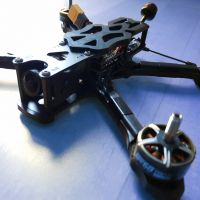
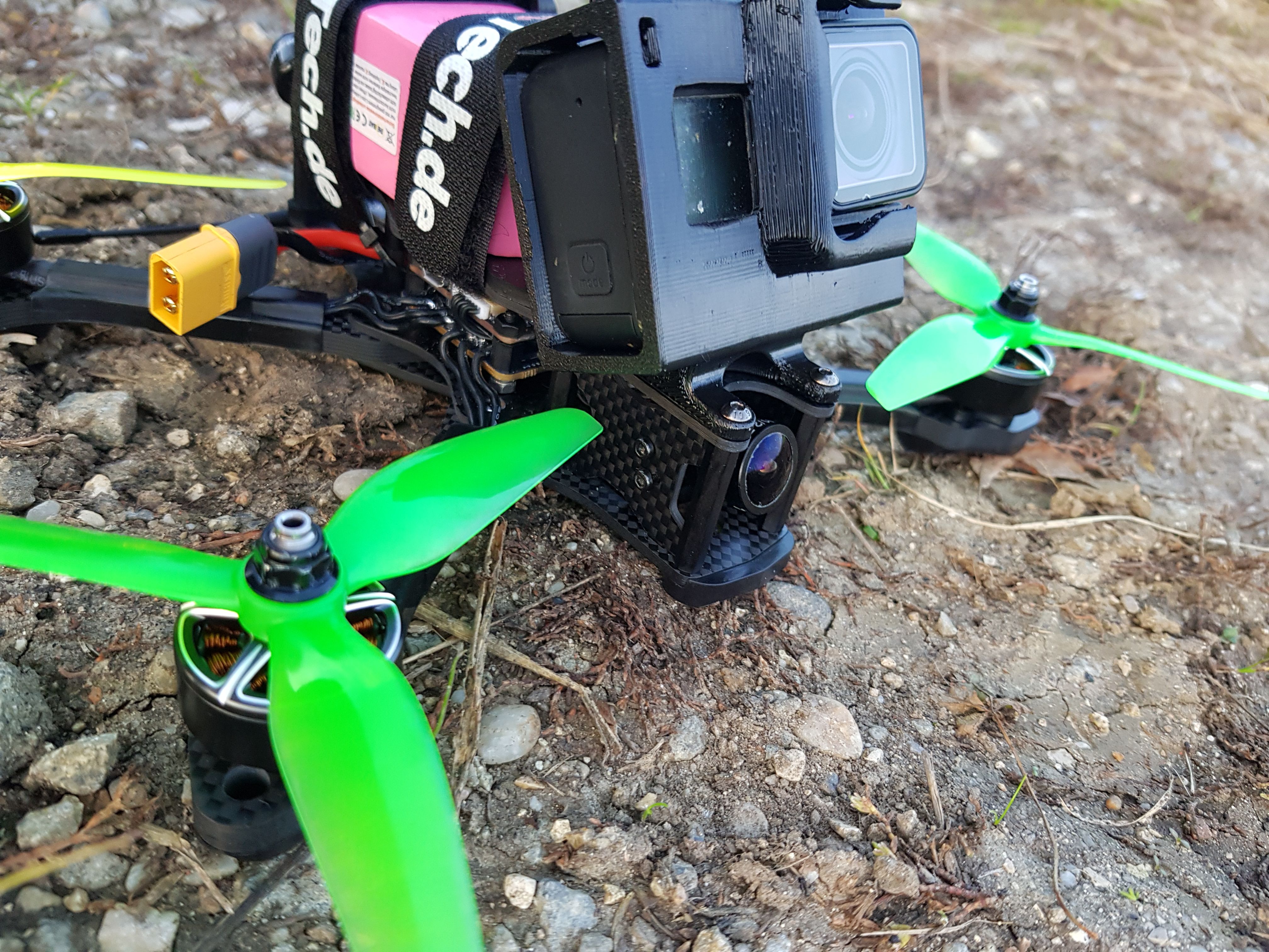
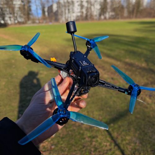
Following the instructions step by step you will end up with a finished frame and attached motors as you can see in the picture to the left.
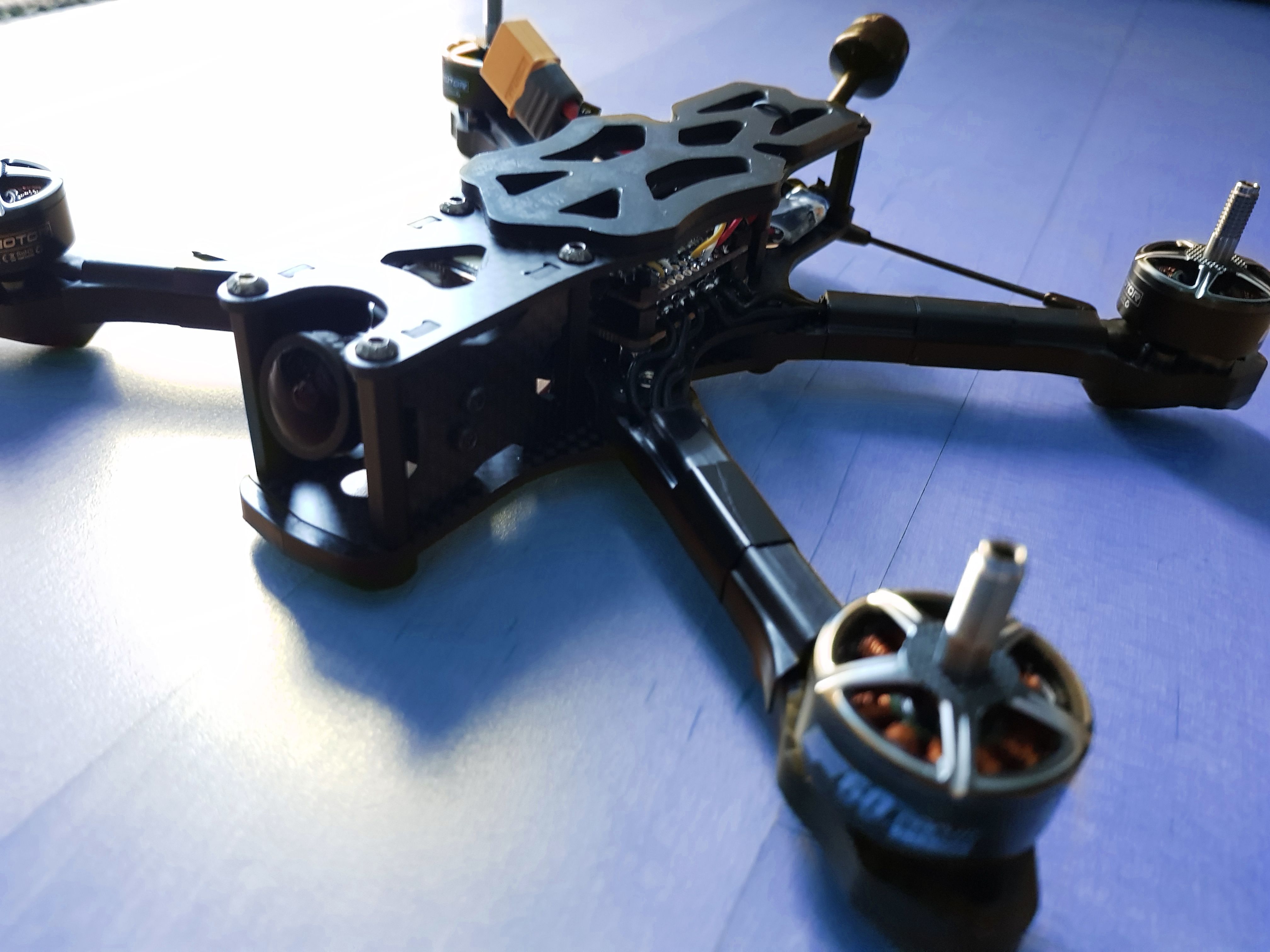
I decided to use the skids delivered with the frame. Be careful to use the M3x10mm bolts only when using the skids. Otherwise the bolts might hit the motor winding. Additionally I used the rubber battery pad for the perfect hold. You can also use the SMA mount to be able to have a clean antenna mount. You can see this in all my pictures. Later on I decided, that a capacitor is still helping in removing a tiny bit of uneccessary noise from the gyro and replaced the SMA mount with a capacitor because of space problems.
Step 2: Mount the stack and solder motor wires

- First of all plug in the FC into your computer and check if it's working. Check the gyro.
- Solder the XT60 connector onto the ESC.
- Montage the ESC onto the screws of the frame. Use electrical tape to fix the wire guards delivered with the Apex Frame in place. Be sure to screw the spacer onto the ESC before starting to solder the motor wires. It's hard to install the spacers once the motor wires are soldered onto the ESC. Solder the motor wire onto the ESC. Afterwards mount the FC and plug it into the ESC with the included cable.
Check your soldering so no motor wires touch each other. The space between the pads can be a little narrow. Use a multimeter to check for continuity on the XT60 plug and make sure to use a smoke stopper when plugging in the first time.
Step 3: Flash and Configure Betaflight 4.1 and BLHeli32 32.7
There's a step by step tutorial done by Joshua Bardwell (JB) in the following video. It should walk you smoothly throughout the process:
Additionally:
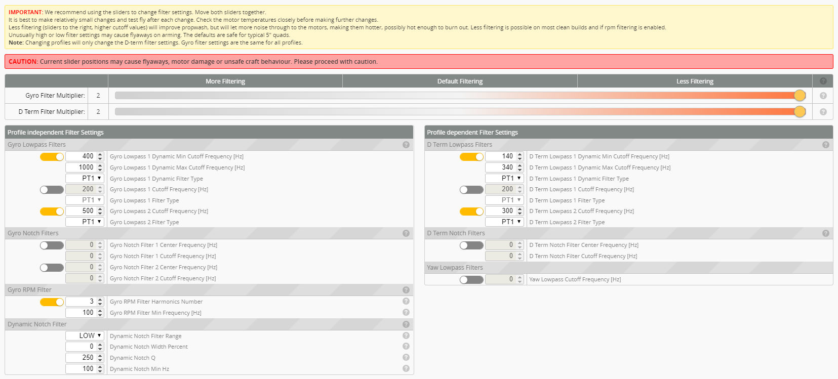
- Set gyro rpm filter harmonics number in filter settings to 3. In a later video JB explains that 1 is providing insufficient filtering and the difference between 2 and 3 is negligible.
- Keep filtering at 1.0. We just wanna test for anything weird first.
- Configure motor directions in BLHELI32 and check if all four are spinning. Important: Set PWM Frequency to 48k. Otherwise you might notice noise on your yaw gyro (which shouldn't be there like you can see in my maiden flight video)
Step 4: Crossfire Nano Receiver

You can see a complete wiring diagram below the last step of this build log.
Solder the crossfire nano receiver onto the flight controller. Output1 goes to RX of FC and Output2 goes to TX of FC. Make sure to use the same UART e.g RX4 and TX4 in my case. Bind the Crossfire Nano with your TX and set up your channels according to your liking.
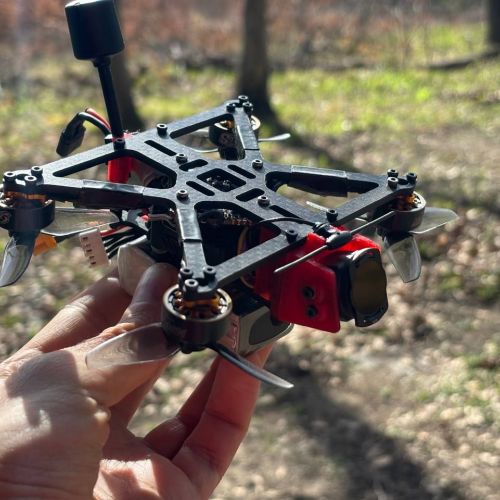
I use the TBS Immortal T antenna and therefore also installed the mount coming with the apex frame. Use the included heatshrink and double sided tape to neatly fix the receiver to the rear of the frame, like seen in the image to the right.
Step 5: Camera and VTX

You can see a complete wiring diagram below the last step of this build log.
Mount the camera and solder it to the FC. If you are planning to use a buzzer (which I highly suggest) you will want to solder the camera and VTX to the same 5V and ground pads located on the top of the FC. Soldering them to the same ground pad has the additional positive effect, that we won't get noise into the video signal from the ground loop effect. So even if you aren't using a buzzer solder those two to the same ground pad for the optimal video quality.
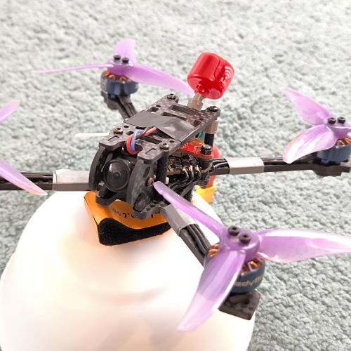
You can see the suggested VTX mounting in the picture to the right. You might wanna bend the antenna cable a little (e.g. by using a cable binder and letting it sit for a day) so it won't touch the IMU of the FC. This would possibly introduce some noise in the gyro. Solder the camera video to the Video In of the FC. Video in of of VTX goes to video out of FC.
Smart Audio goes to an empty TX slot on your FC. This enables you to use smart audio and the new betaflight 4.1 vtx tables. To configure it you just need to set your VTX Table in the Betaflight Configurator to the one you can download on the Betaflight Github Wiki (https://github.com/betaflight/betaflight/wiki/VTX-Tables). You want to donwload Smart Audio 2.0 for this VTX.
Put everything back together and you should be ready to maiden! Since the build is really tight you might want to "install" your lipo straps before installing the top plate.
Step 6: Maiden
You should do a technical maiden before and check the heat of the motors. Also insert a sd card and enable blackbox logging.
Use Pidtoolbox or Betaflight Blackbox viewer to check your pre filter gyro noise to get ready for the last and final step, the tuning.
Video of my quads maiden flight (default tune with rpm filter, no hypersmooth and no nd filter):
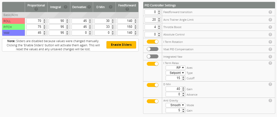
Step 7: Tune
This tune is heavily focused to get a locked in stick feel while maintaining extreme responsiveness.
To achieve this the tune will heavily rely on high Feed Forward and an unusually low I-Term relax for freestyle. The feed forward is really on the edge but isn't resulting in any unpleasant overshoot. Also the tune will aggressively boost Dmin to the D value to counter Propwash and wobbles that may occure due to too high I-Term in sweeping turns. Additionally it really uses a low amount of filtering. High D values can amplify noise in the gyro by 100x or even 1000x resulting in overheating motors. So I suggest to start at lower D Values, D Gain and overall lower PID's and slowly rising it to the desired value. Always check for hot motors.
Video of the current tune in action (less Dmin gain, Tune above should have much better Propwash handling):
Wiring Diagram

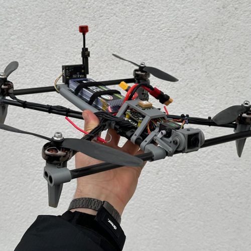
Photos

Part List
Show stores (6)
Guides & Reviews
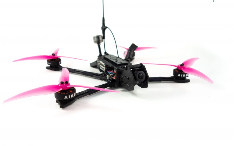
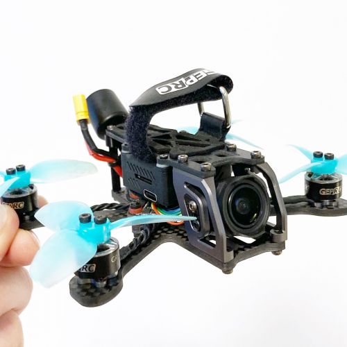
AirbladeUAV has done it again and this time they've brought long range to the 5" class! Based on the popular Transformer Mini, the new Transformer 5" Ultralight adopts a lot of the same design philosophies with larger props and more payload capacity. It can fly upwards of 20 minutes on a 4 cell Li-Ion battery pack and in ideal conditions it's got a range of over 4 to 5 miles. In this guide I'll walk..
Read more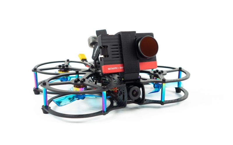
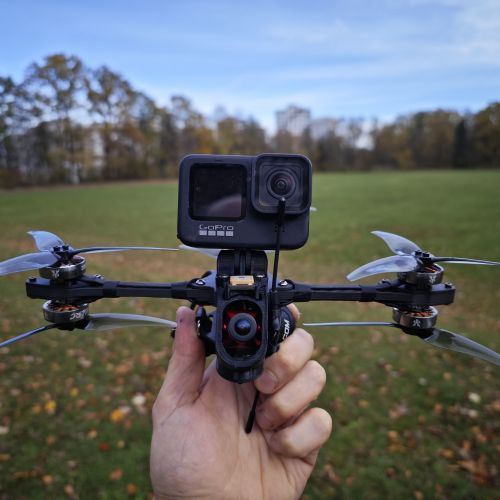
With the release of the DJI FPV Drone cinematic FPV has become a lot more accessible, but you certainly don't want to crash a $750 drone! The QAV-CINE Freybott is a compact, lightweight cinematic FPV drone that can take a hit and keep going. It's a lot safer to fly indoors and around people. With a naked GoPro or the SMO 4k you can capture some great stabilized footage. In this guide I'll show you..
Read more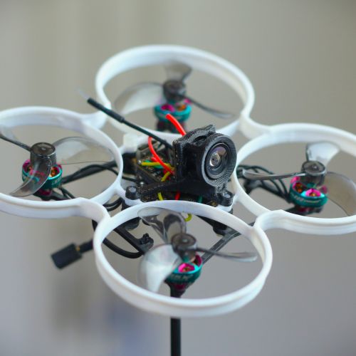
Hi, is there anything you would change about this build now? Thanks.
I already did some changes to it. Although I think that the build I post here is still really good and offers an amazing flight.
First one was the ESC not initializing correctly sometimes (~2 out of 10 times). That was kind off anyoing, but I think I just was unlucky with the ESC i got. This was a bit anoying but nothing too bad.
Additionally I saw quite some recommendations on the RevoltOSD Flight Controller using FalcoX firmware. I was very sceptical about their firmware as they make nonsense marketing claims. So after seeing people switch and somehow I got manipulated to test it as well... It really feels much better then betaflight. Feels like the quad is on rails and you are really in control. While I was already at it I also went for the Hobbywing Xrotor 60A ESC...
So yeah while this build still is really nice. The new changes made it amazing :D
I also switched to aluminium screws to shape of some weight.
Thanks for the prompt reply. I really appreciate that.
BTW, which battery did you go for and what kind of flight time do you expect out of this build?
i have different ones. I have one tattu r-line v3 1550mah I tested and 6 mylipo 75C 1600 mah. I get around 2 - 5 Minutes of flight time. Depends on how much I am pushing the quad...
Do you still have a picture of how the Hobbywing 60a ESC fitted in your frame? I'm also building an apex with that esc and it's a real struggle to get it all fit together. I'm also worried if the capacitor touching my vtx antenna might cause some distortion in my video...
I didn't find any picture where it's visible, but I faced similar issues. I got rid of the vtx antenna mount included by the frame and just used a zip tie to mount it to the top plate using electrical tape to make sure the antenna connector is not touching the carbon directly. The connector is indeed touching the capacitor, but that didn't cause any trouble for me. Just make sure it's not touching the legs of the capacitor and I think you should be good.
Wow, thanks for your quick reply! Okay so far the antenna is only touching the capacitor, not the carbon or anything else, so I might me lucky with how it is right now. FC is the only thing that I need to install, so well see this weekend how the first flight will go.