
This is a super-light, and super-tight build that's meant for long-ish range. To be honest, I'm not sure how far it'll actually go, or for that matter, how far I'll actually take it. But because it's designed to be sub 250g, you should be able to fly it anywhere. This particular switchback is set up on crossfire, so the only real limitation it should have on range will be battery capacity and/or video link.
I knew going in that this build would be a challenge for me. I've never worked with 20x20 components or such a tight/integral stack system. I hope that the information I've included below is helpful to anyone who follows behind me.
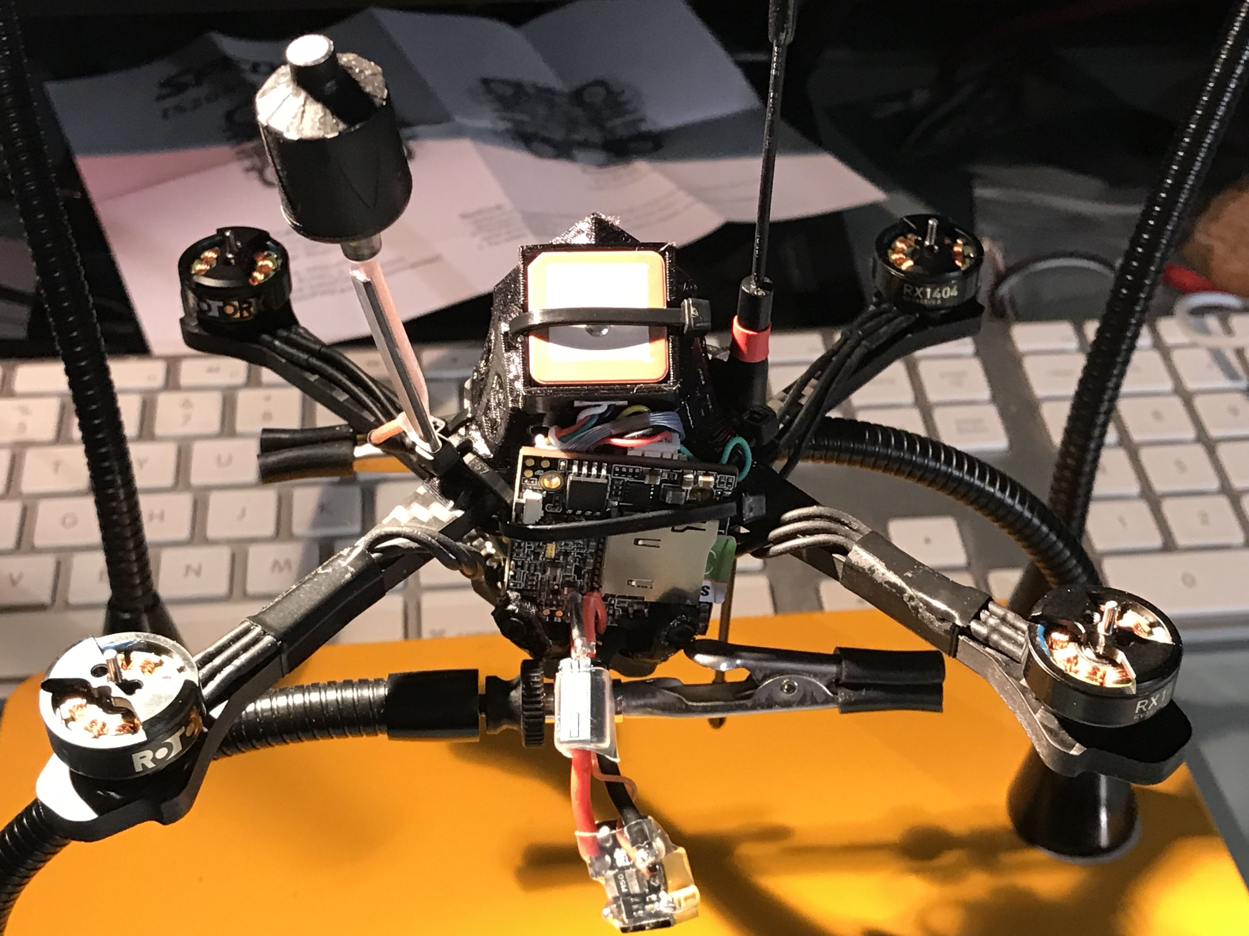
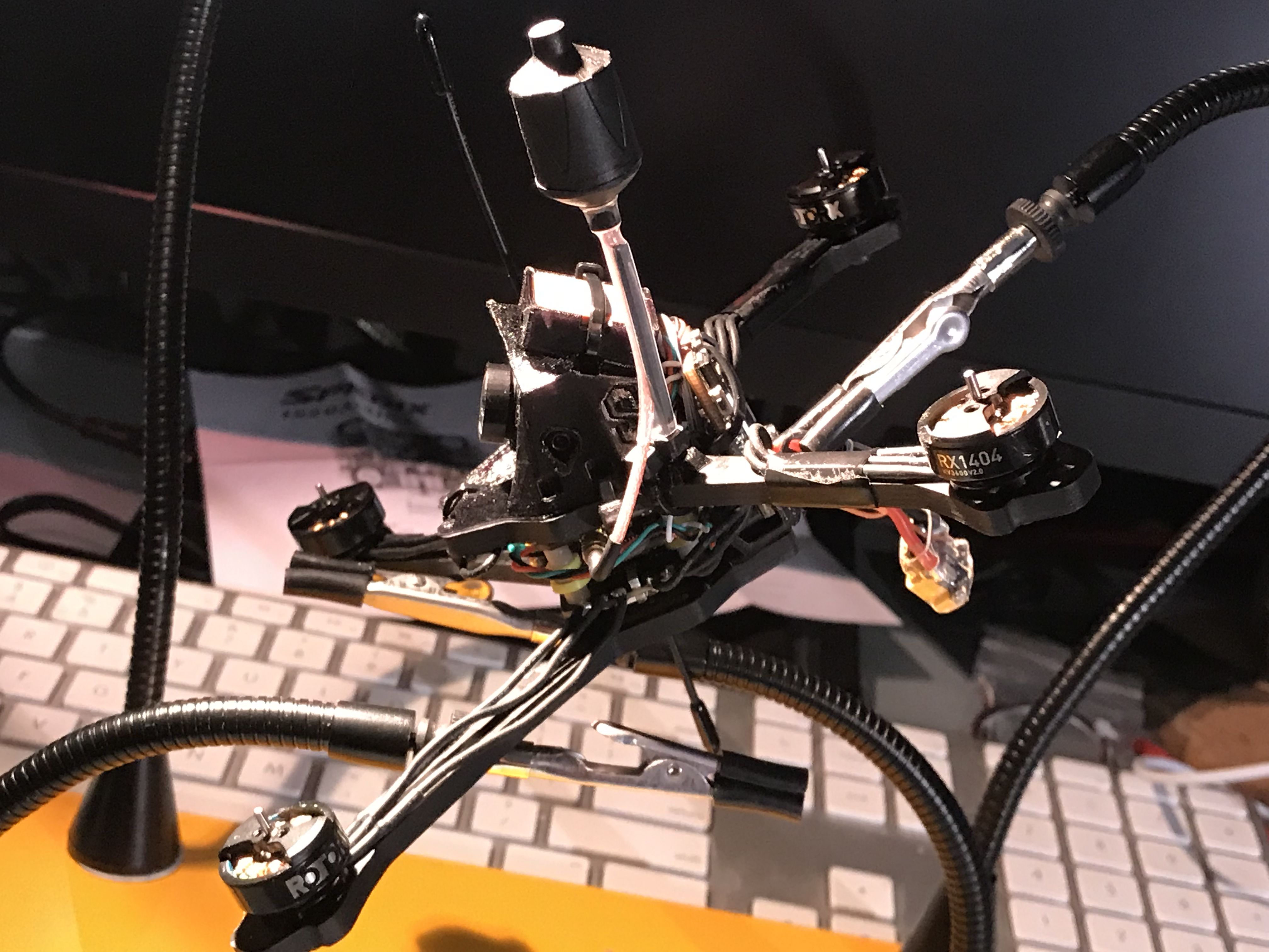
Because of the lack of space (by design) on this build I did several dry fits of the main stack components, and I've included several pictures below to walk through the build process. I highly recommend performing a dry-fit of this stack without any wires or solder applied so you can get a feel for how it goes together and so that you can begin to visualize where the wires are going to need to be routed. The steps below are written for this exact build. Your build may be different, but the general principles apply.
Note from Experience: If you aren't comfortable soldering small joints in tight spaces, don't build this quad. You've been warned!
Note to Builders. I assume you know how to flash firmware, bind receivers, make models in your radio, and work with Betaflight. If you don't know those things, YouTube is your best friend right now. Go get your learnin' on!
Dry Fit
-
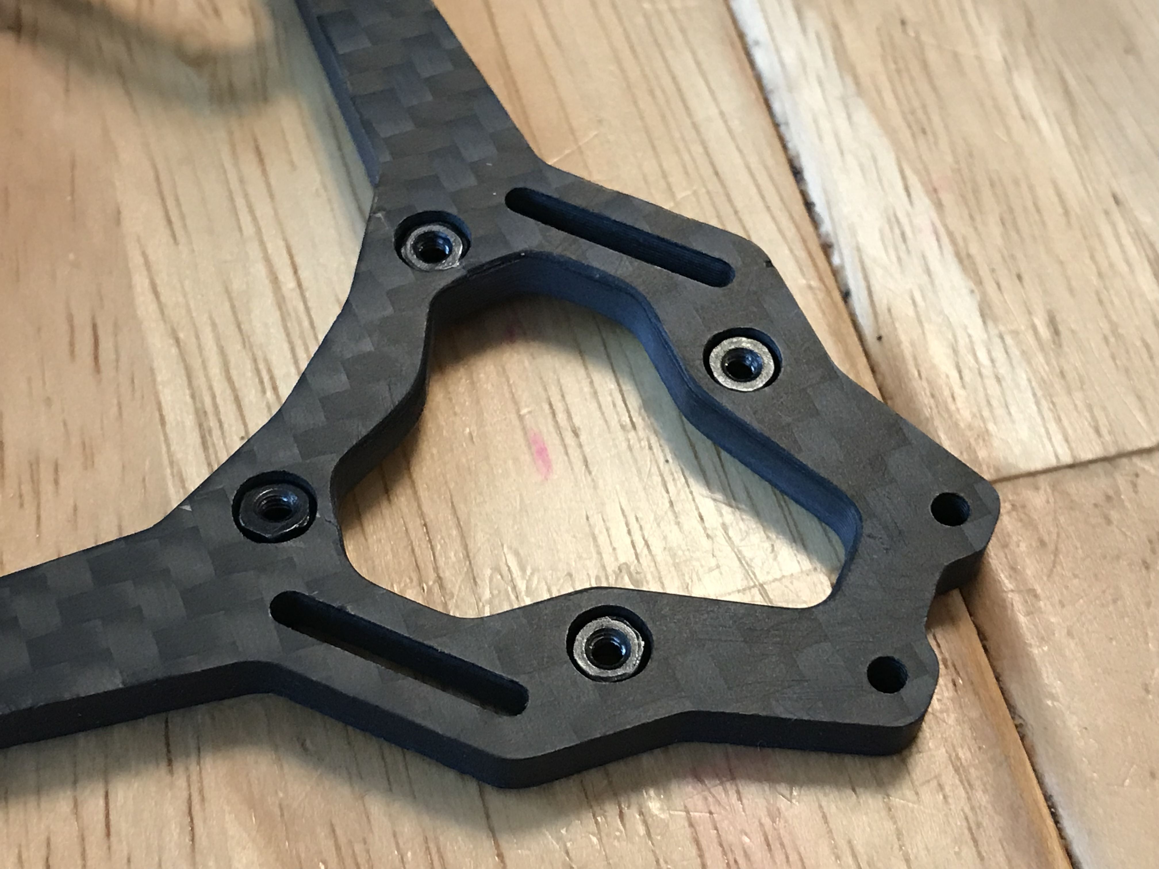
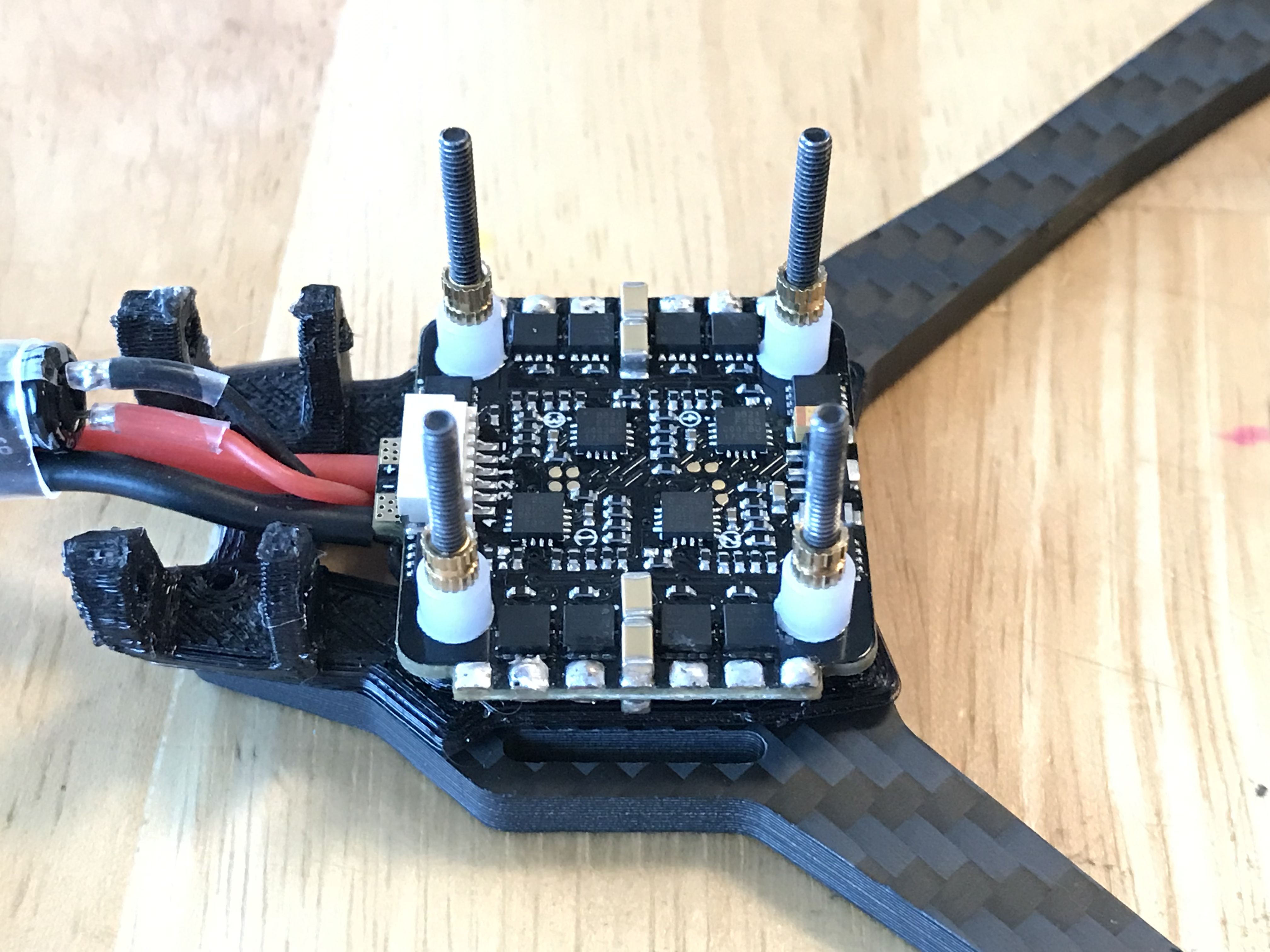
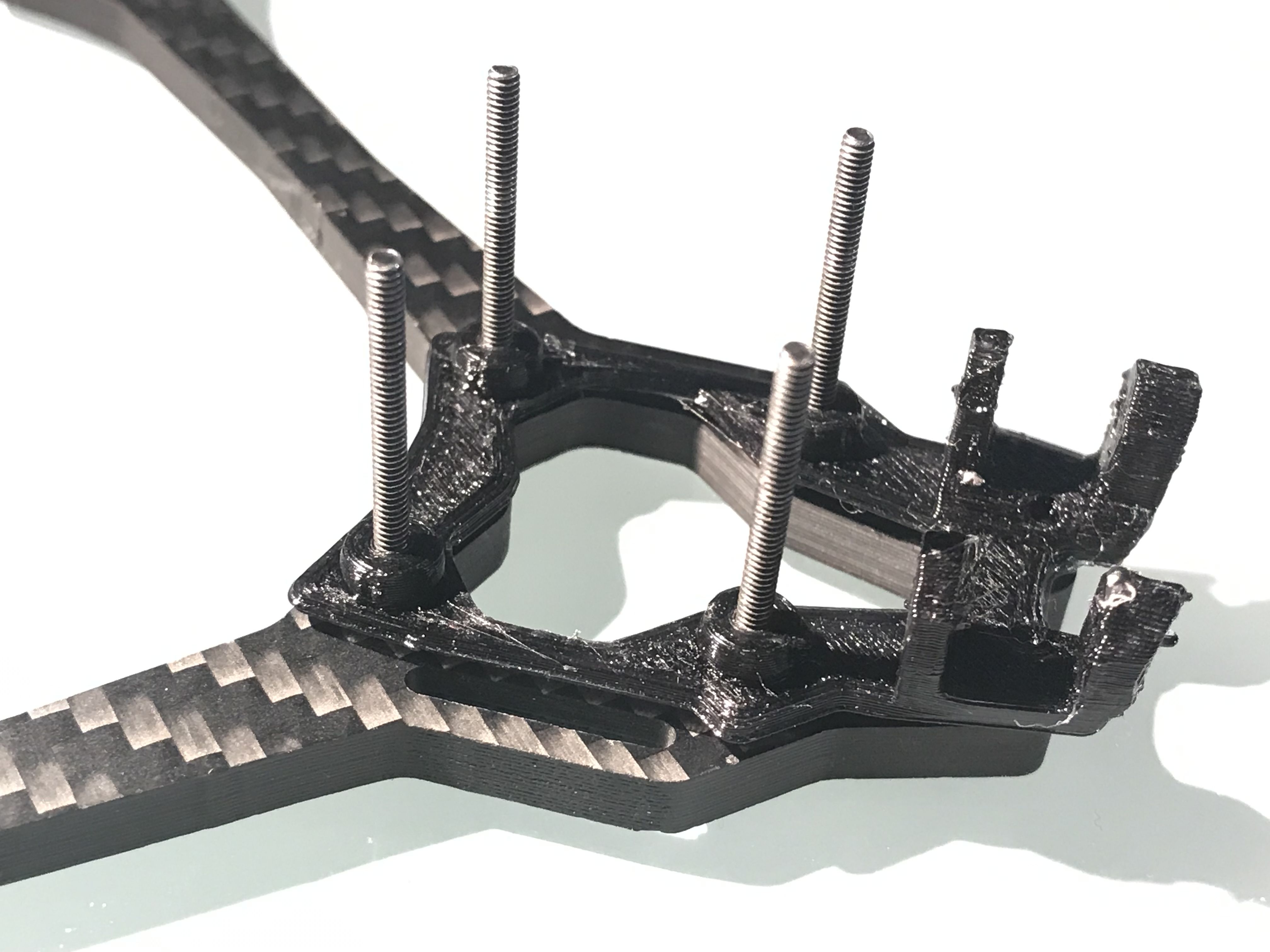
Bottom plate assembly: Each arm-pair is identical, so pick one and orient it so that the four (4) counterbored holes for the stack screws are facing down (away from you). Position the TPU mount/backpack pad on the top of the bottom plate so that it lines up with the four (4) thru-holes for the stack bolts. The foure(4) "bumps" on the tpu should be facing up, and the backpack bracket should be on the opposite side from the arms. See the picture below for reference. Thread the four (4) long screws that came with the kit into the TPU from the underside of the bottom plate such that the screw heads are full seated inside their counterbores.
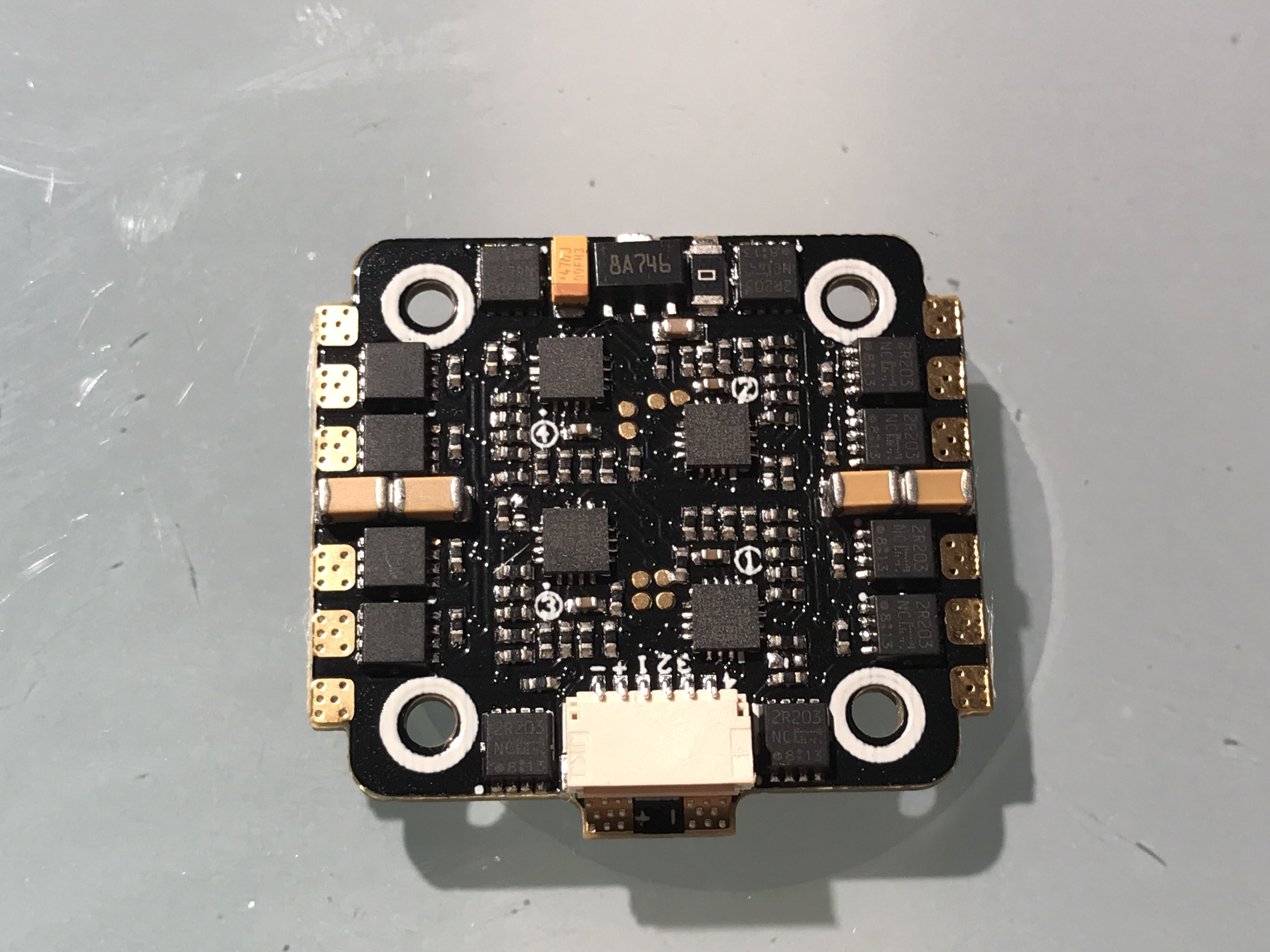
- ESC Assembly: Place the ESC directly on top of the TPU insert from Step 1 and orient it according to motor number and position. The Spedix 20A 4n1 I used for this build has helpful screen print numbers on the PCB that show which set of motor pads are motors 1-4. For this build, that means that the ESC harness port is facing the rear of the stack (away from the bottom plate arms) and is facing up.
NOTE: This next step differs from the advice of RotorX on the Switchback assembly. RotorX does not recommend the use of threaded spacers. Use extreme caution to ensure that no contact is made between the stack laters.
-
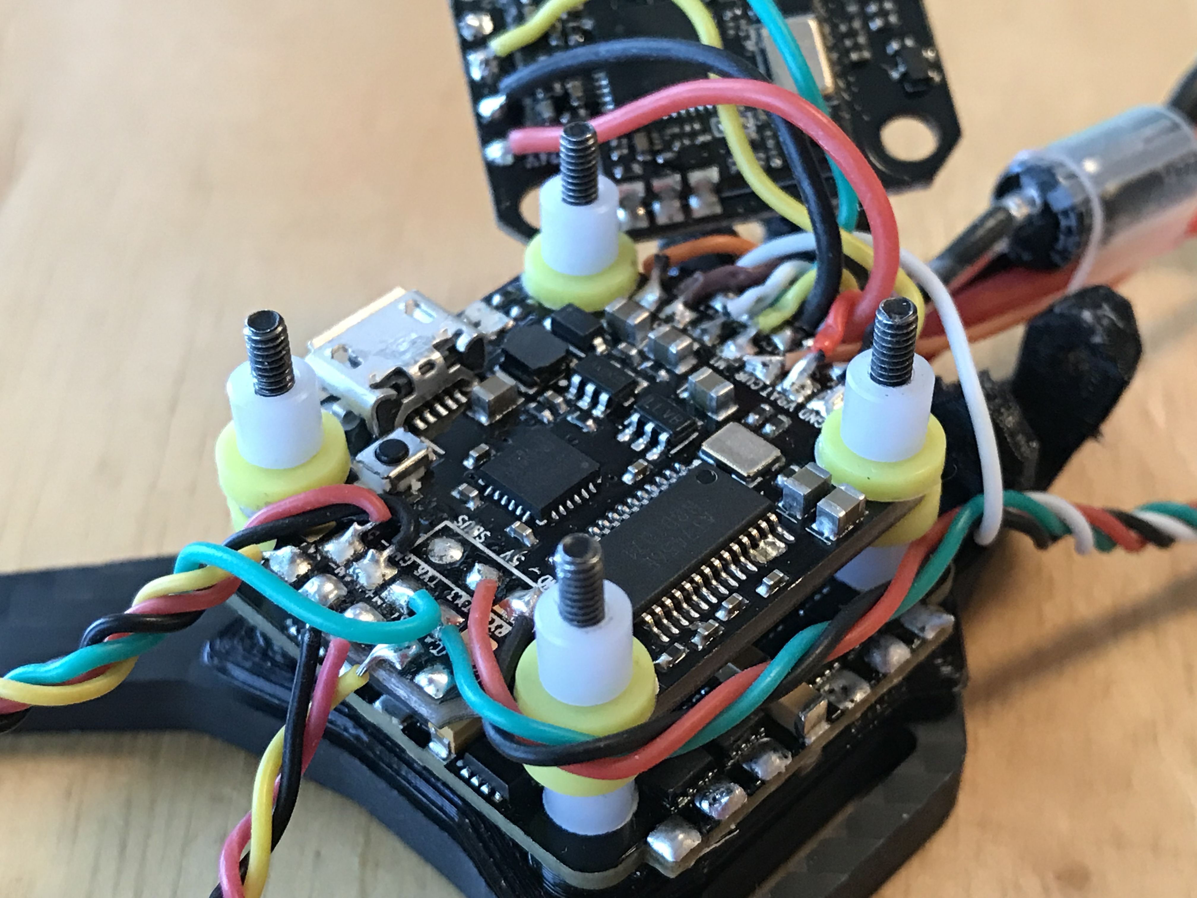
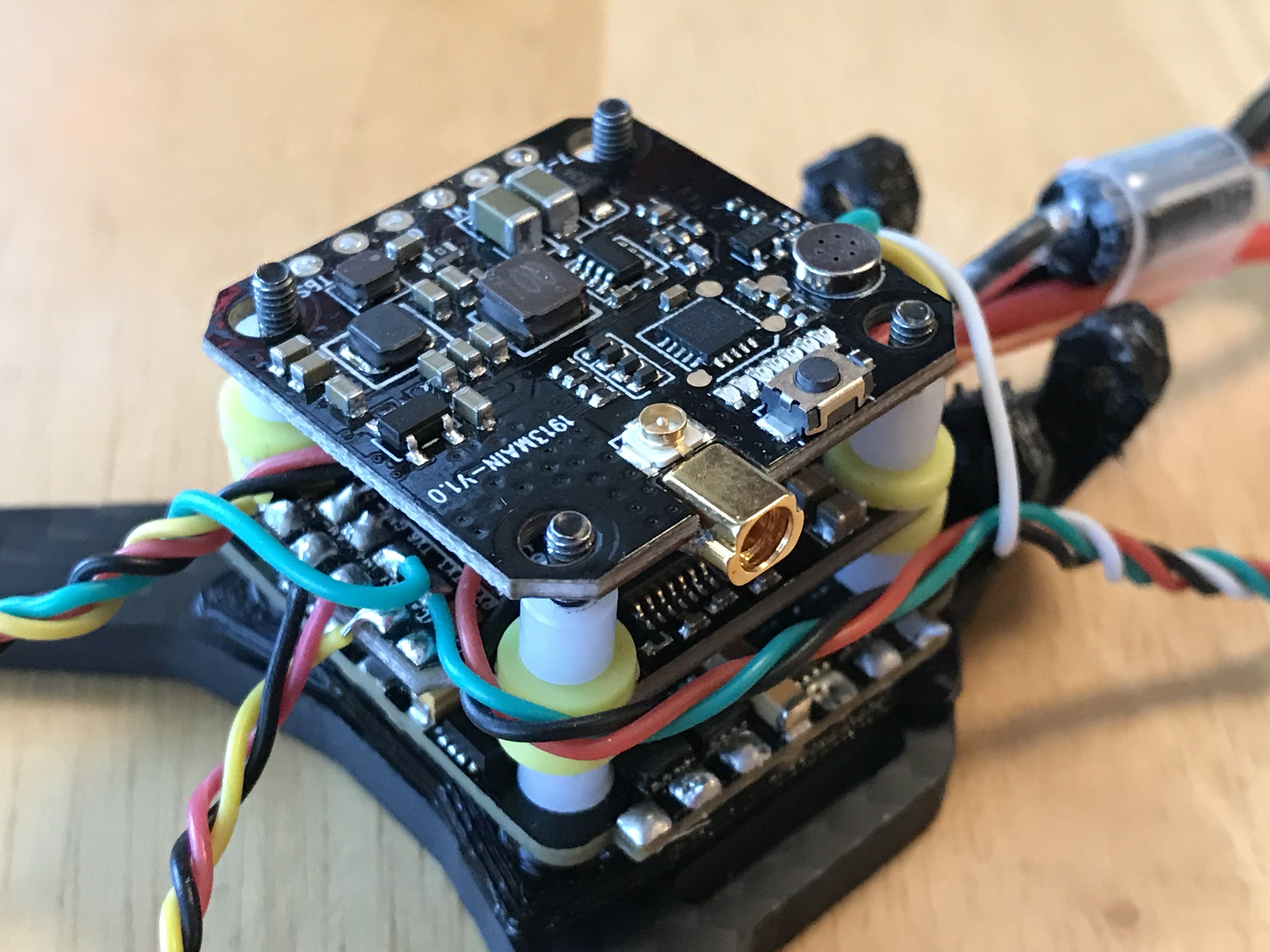
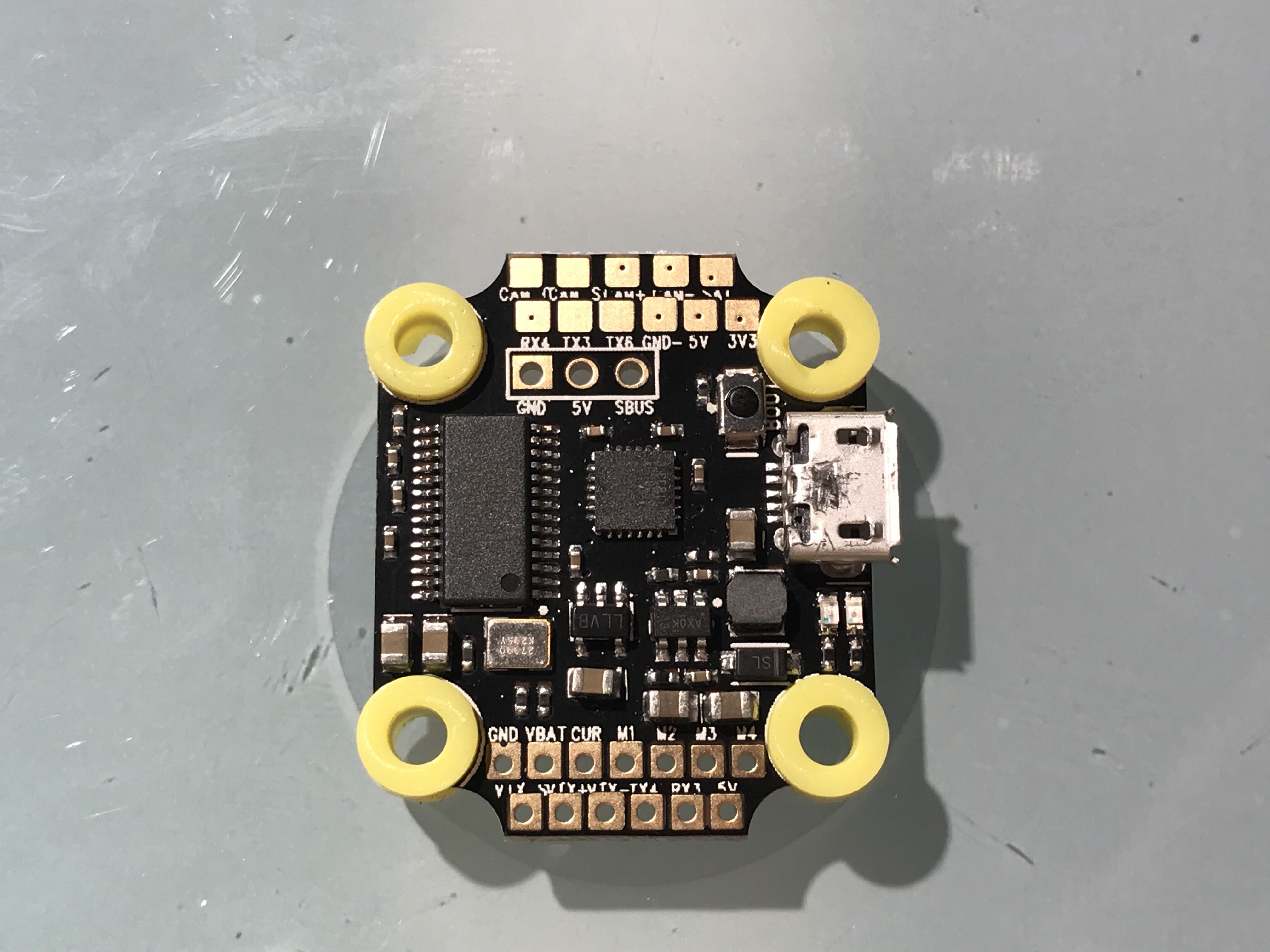
FC Assembly: Place four (4) of the white 2mm nylon spacers over the screws - they should slide down over the long screws and rest against the ESC. Take 4 of the threaded press-nuts that came with the CLRacing F4 Mini and thread them onto the screws, overtop of the nylon spacers. Running them down to finger tight is sufficient, but make sure that the ESC is full contacting the four (4) TPU bumps on the mount/backpack pad. Install four (4) of the yellow vibration damping "gummies" into the 4 screw-holes of the FC. Orient the FC so that the USB plug is facing up and is on the right side of the frame. This is proper orientation for flight. It's worth noting that the screen-printed pad labels are all written such that when read in a left-right and top-bottom format, the board is oriented correctly. Slide the FC over the four (4) stack screws and press it over top of the threaded press-nuts. No need to force them into place, flush with the nylon spacers is fine.
-
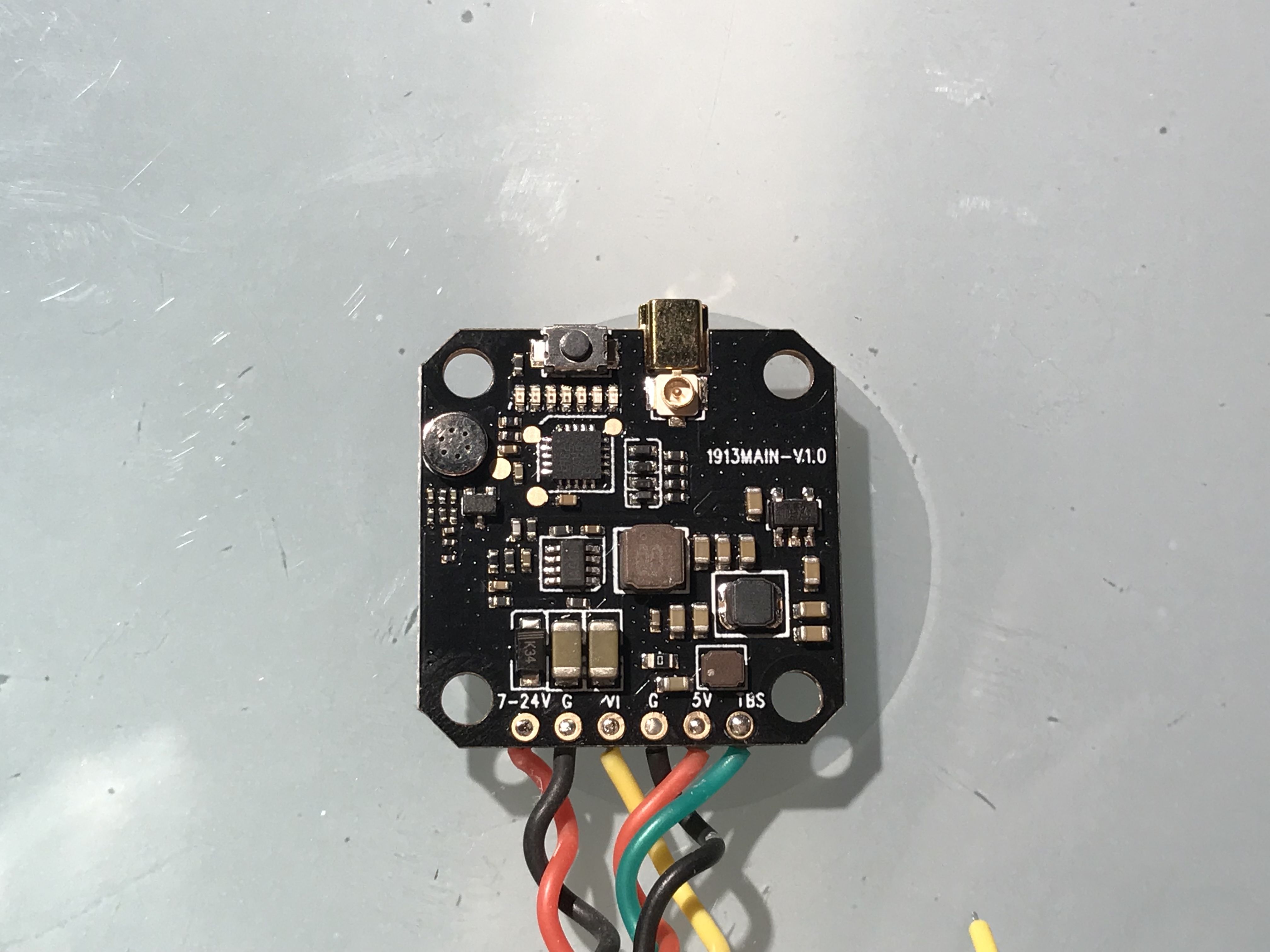
VTX Assembly: Slide four (4) more nylon spacers over the four (4) stack screws. Orient the VTX assembly such that the selector button and ufl connector are facing down and to the right of the frame. This will result in the pre-soldered wire harness facing left.
-
Top Plate Assembly: Slide four (4) more nylong spacers over the four (4) stack screws. Orient the top plate such that the arms are facing the rear and the four (4) counterbore holes are facing up. Place and gently hold the top plate over the four (4) stack screws. Locate one (1) of the small M2 metal nuts and place it into one (1) of the counterbored holes. Insert your 1.5mm driver into the head of the stack screw that you just placed the M2 nut over. While gently squeezing the two (2) arm plates together, begin tightening the stack screw until it begins to thread into the nut. Only turn it until it has caught the threads. Repeat the nut installation process on the opposite corner from the one (1) just installed, threading the nut only until the nut has caught the threads. Repeat for the remaining two (2) nuts. Once all four (4) nuts are installed, alternate turning the four (4) screws in a star pattern until the threads are just protruding past the tops of the nuts. DO NOT overinsert the screws.
-
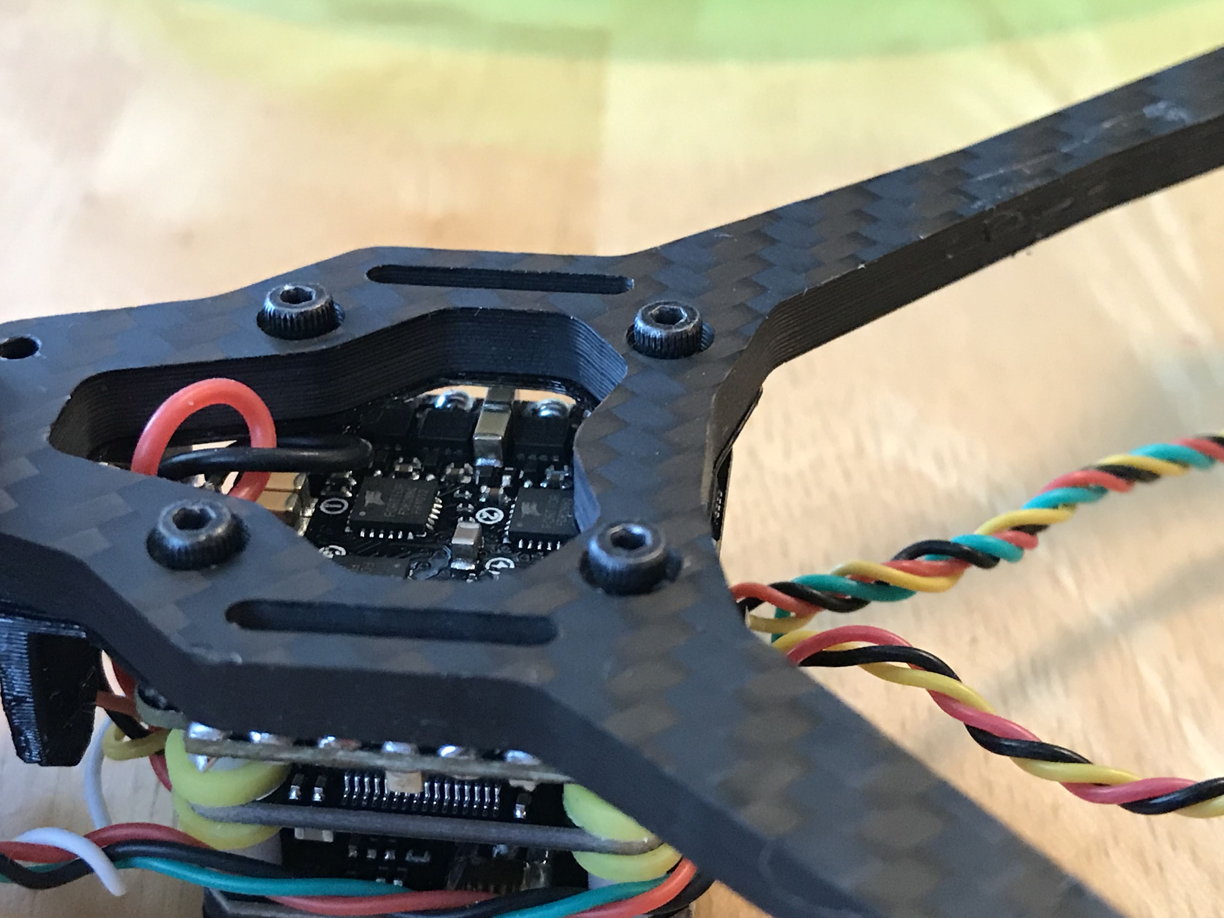
Check every layer for clearance to the carbon fiber and the adjacent stack layer. Now is a good time to take note of the clearance between stack layers for wire routing. If contact between the layers is occurring, check that you have all nylon spacers installed and that you have not overtightened the mounting screws. The bumps on the mount/backpack pad should not be fully crushed and there should be clearance between the top plate and the VTX selection button.
-
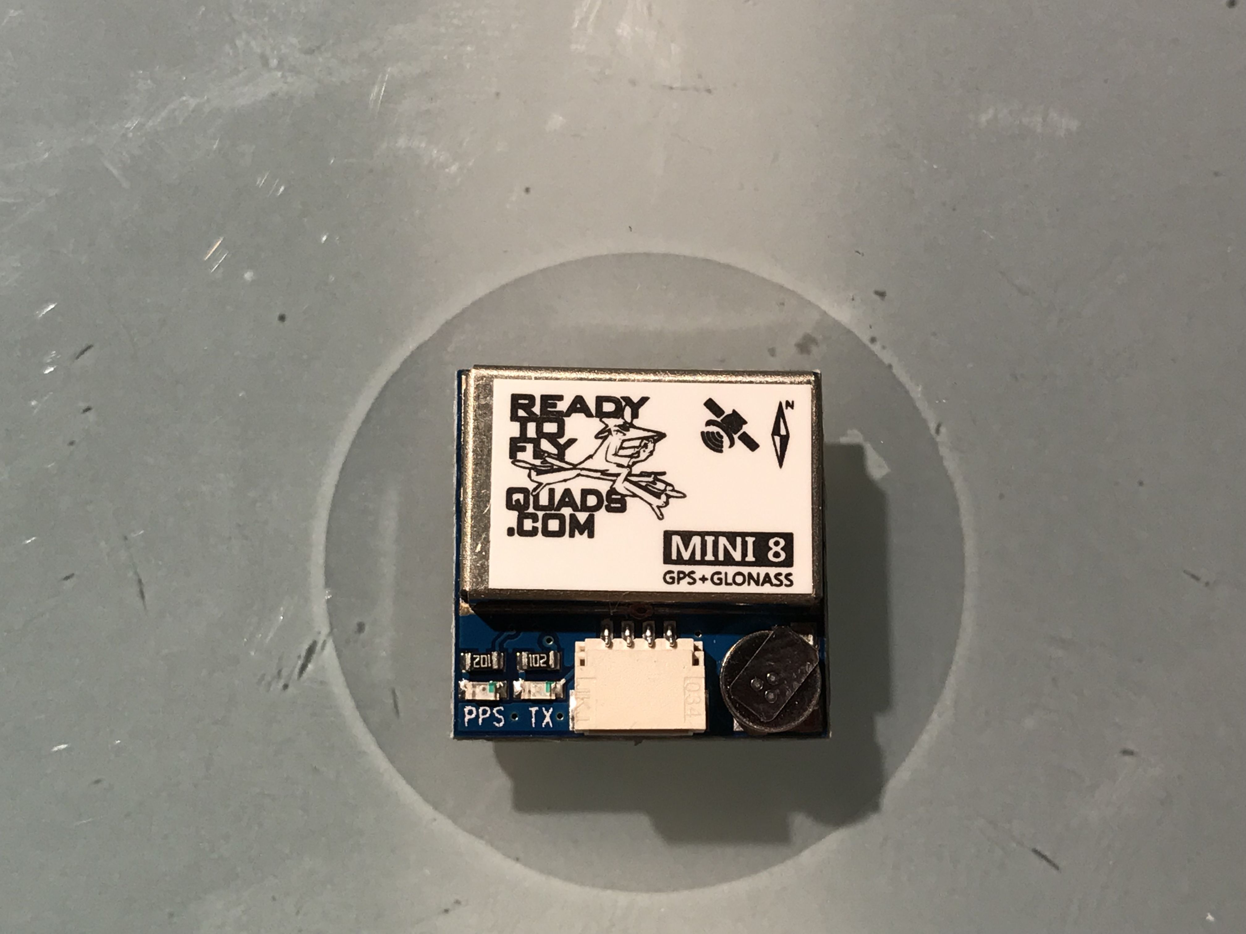
Install the Ublox antenna into the TPU camera hood, along with the immortal T. Place the assembly over the top plate in position, and take note of possible wire routing options.
- Disassemble the components carefully and set aside.
Build
-
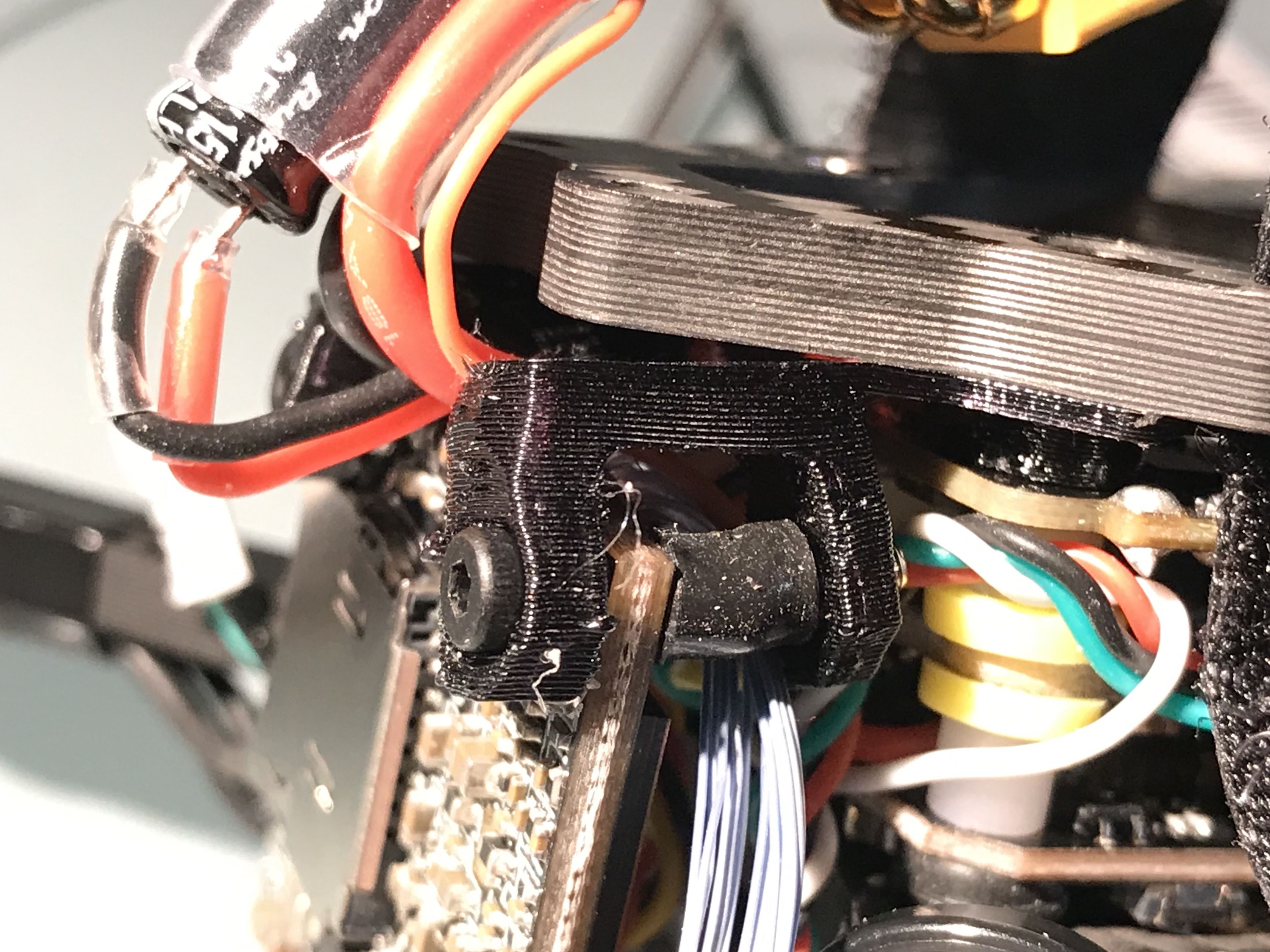
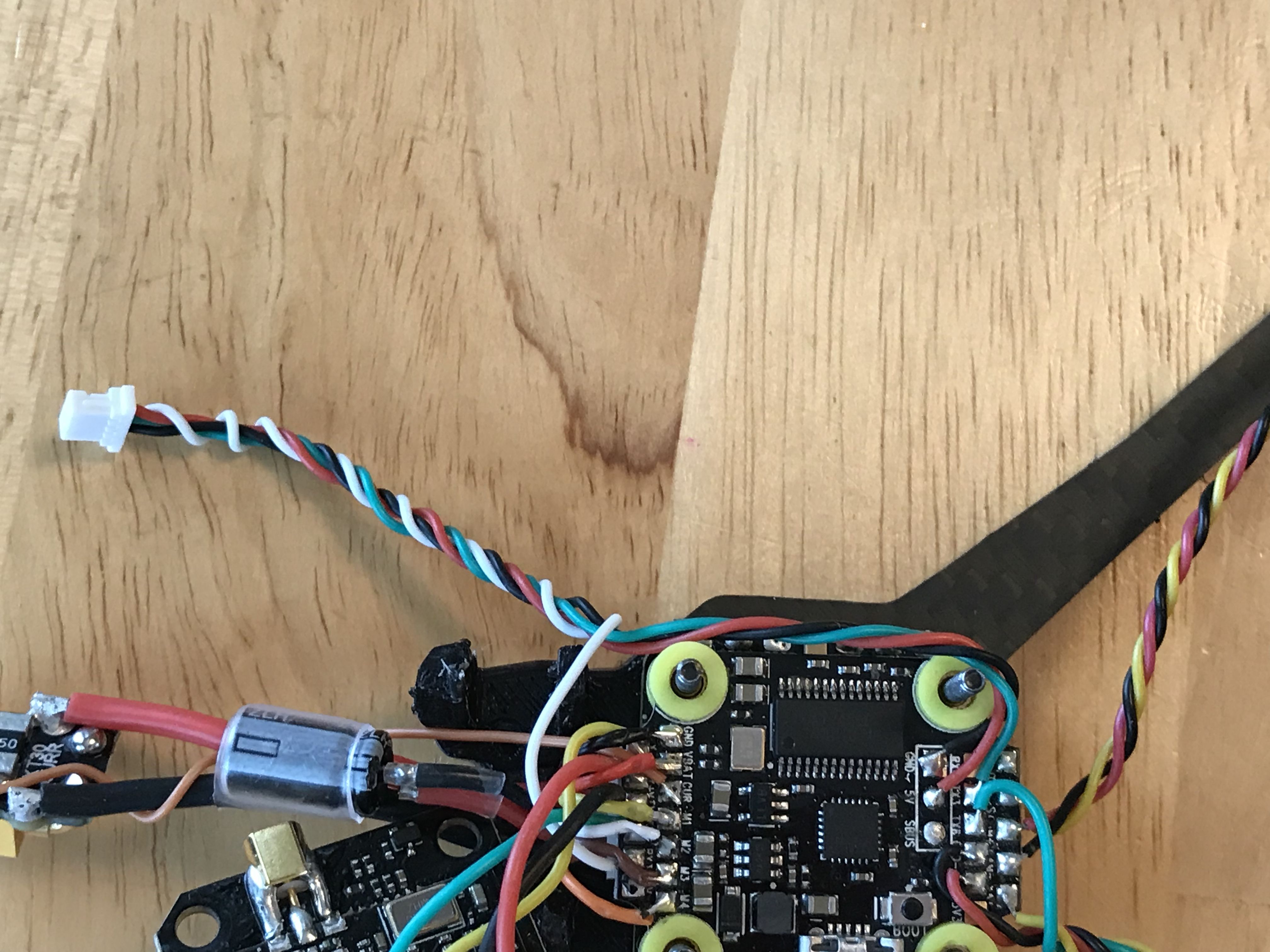
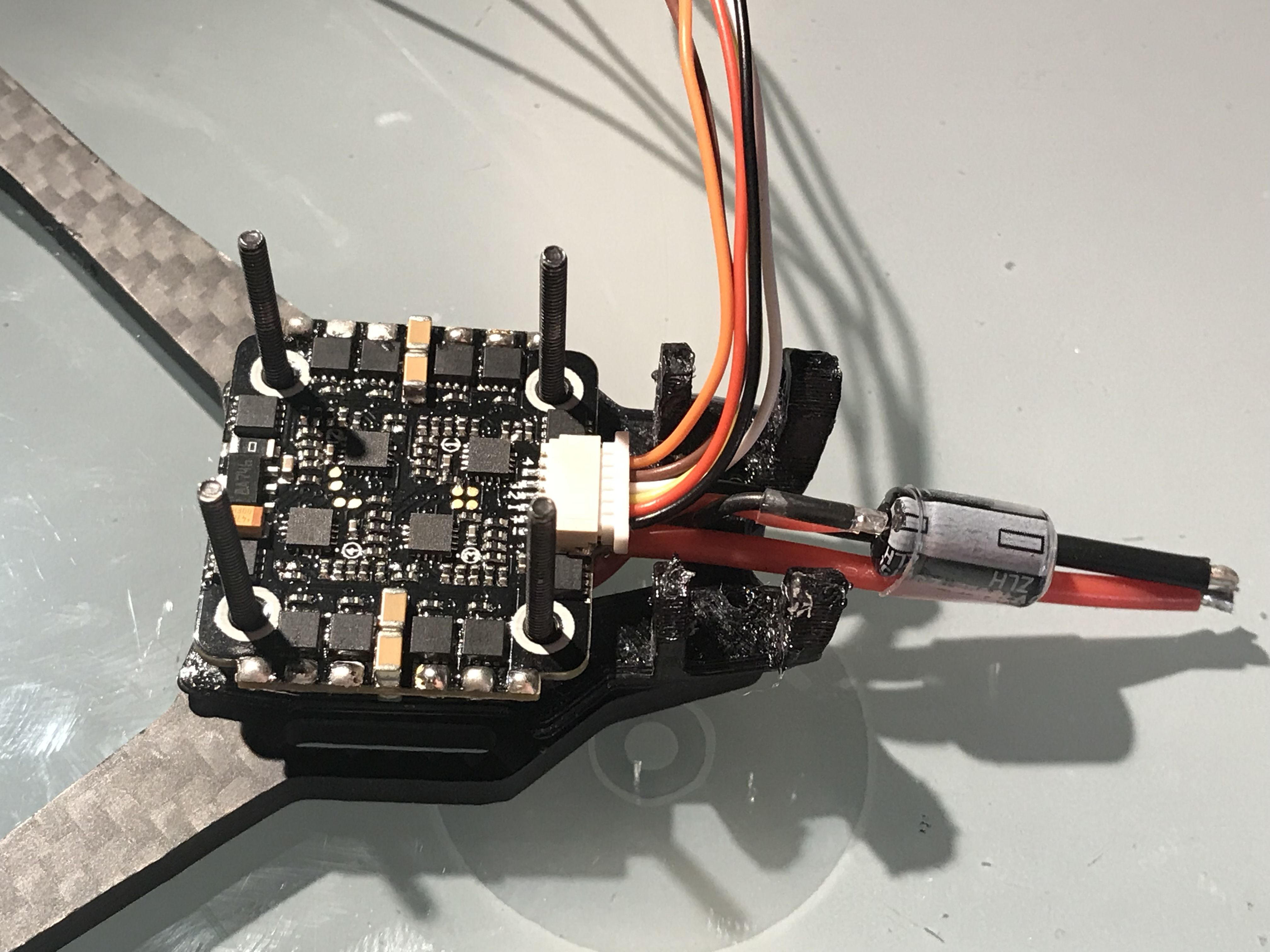
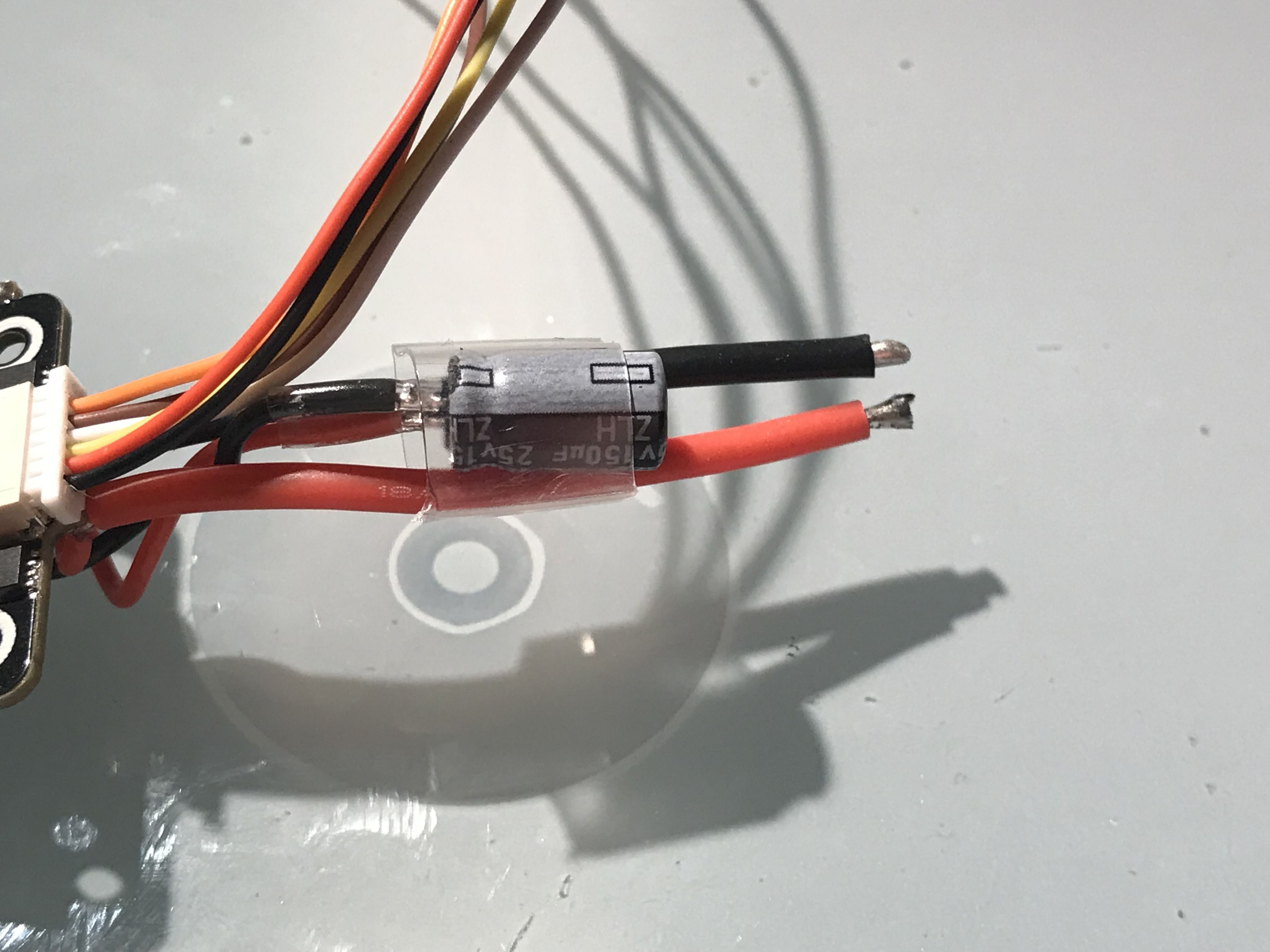
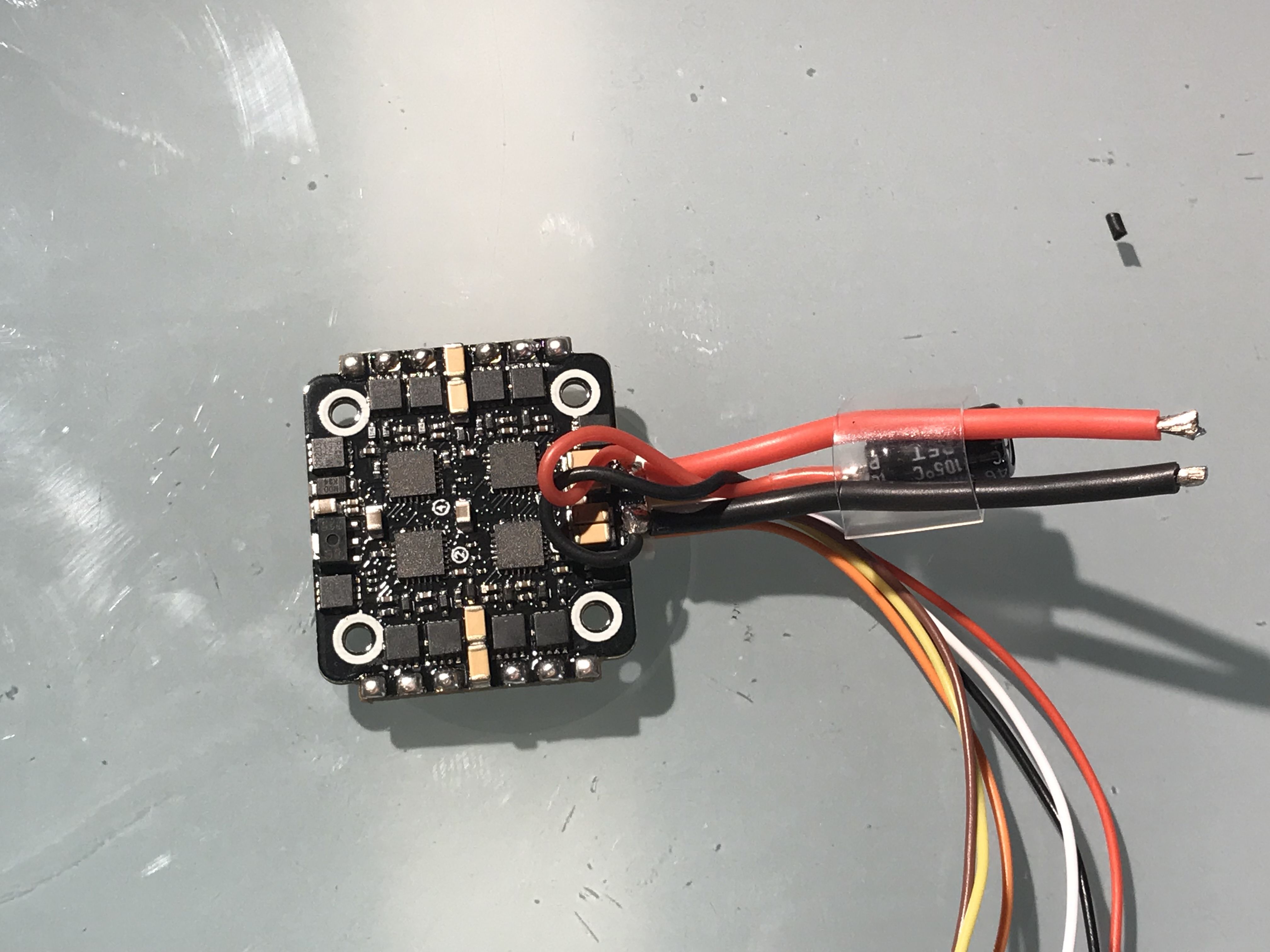
ESC Assembly: The Spedix ESC has tinnable pads on both sides of the PCB so that you have options for orienting the ESC. For this build, tin the motor pads on the same side as the wire harness connector, and tin the battery pads on the opposite side of the wire harness connector. Tin the battery wires and solder them to the previously tinned battery pads - rear orientation is fine. The diagram included with the ESC strongly encourages use of the included capcitor. Because of the space constraints of the Switchback I chose to use small gauge wire extensions to connect the capacitor to the battery pads. I then twisted the wires and used heat-shrink to attach them to the main battery leads. Before you set the heat-shrink, place the ESC Assembly into the frame to make sure that your battery leads and capacitor have room to move without contacting the frame. Once you are satisfied with the location of the capacitor, set the heat-shrink. See the pictures below.
-
ESC Harness Trimming: Install the wire harness into the connector on the ESC and install the ESC as done previously in Step 2 of the dry fit. Install the FC as done previously in Step 3 of the Dry Fit (exclude the threaded press nuts at this time). With the FC in place, position the ESC wire harness as desired and trim the wires to length. Make sure to leave a little slack. Disassemble the stack and tin the wire leads - use caution as the wires supplied are not silocone sheathed and will melt.
-
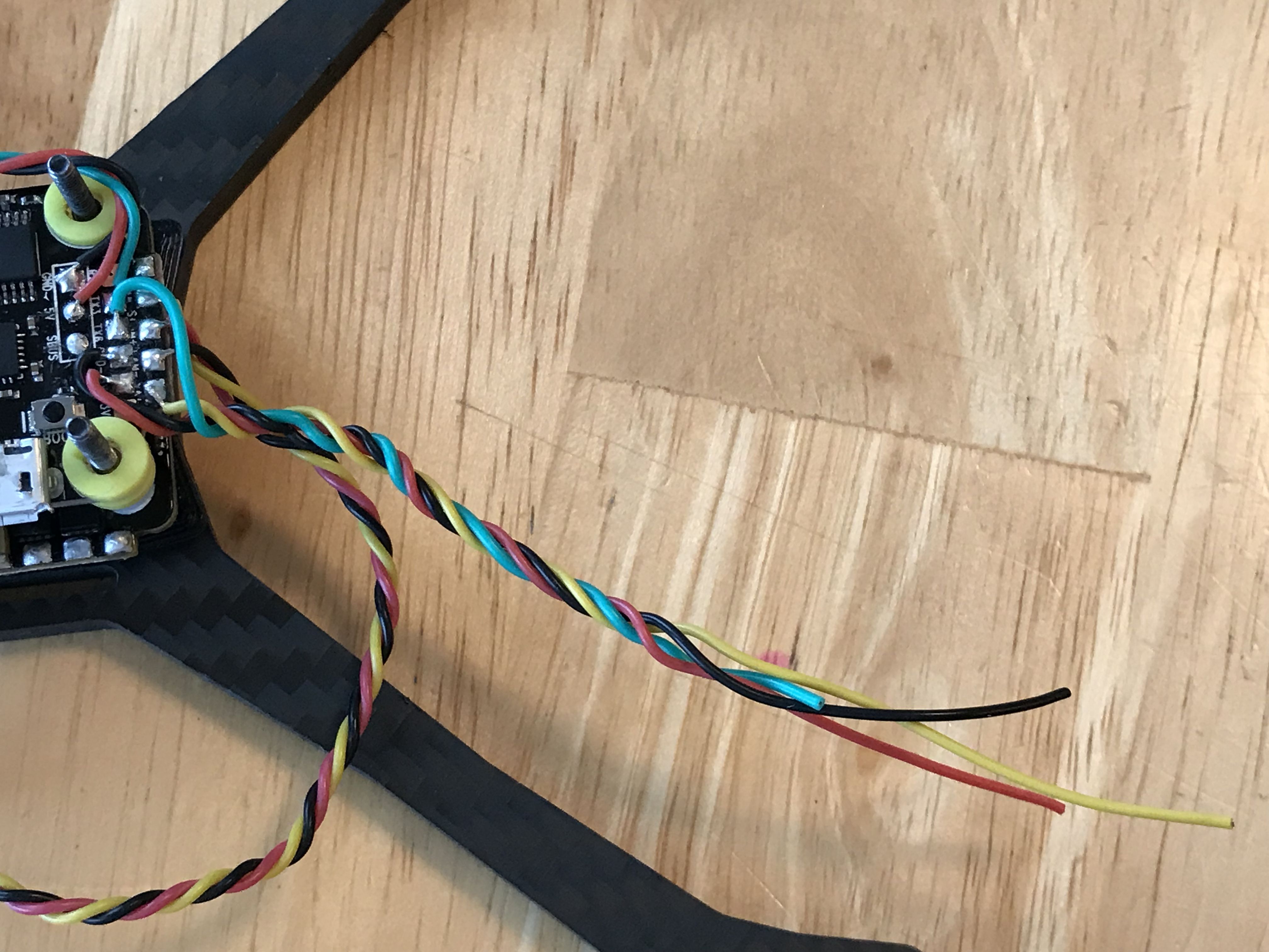
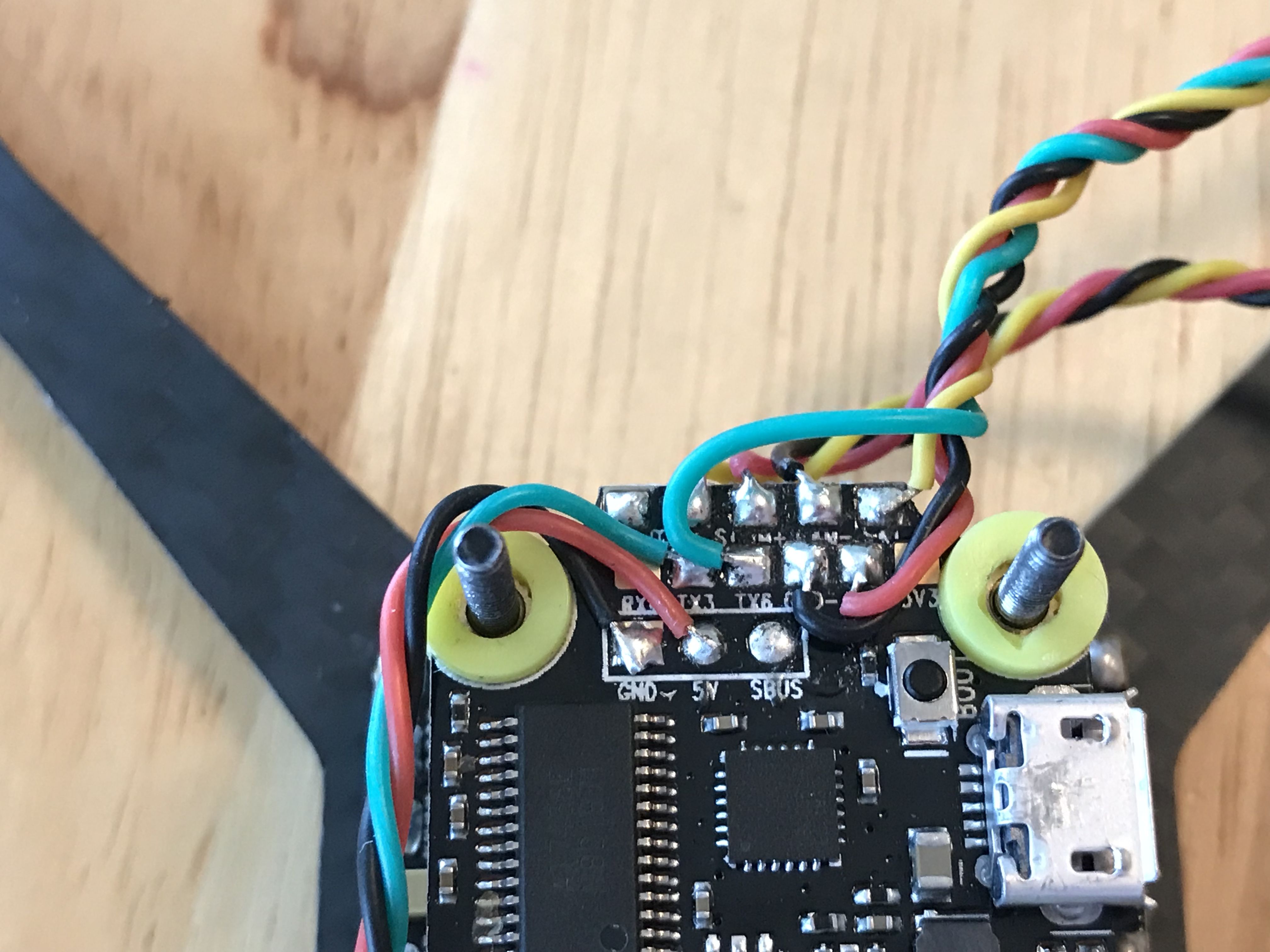
Flight Controller Pre-Assembly: Tin all of the necessary pads. TX3 and RX3 are used for the GPS connection. TX4 is for VTX smart audio connection. TX6 and RX6 (SAT) are used for crossfire nano connection. The GPS wire harness will need to have different length leads because TX3 and RX3 are on opposite ends of the FC. Install the nylon and threaded spacers over the ESC as mentioned previously and place the FC onto the stack until the yellow gummies just contact the white nylon standoffs. This is the perfect time to get your FC set up in betaflight, so go ahead and do that now.
-
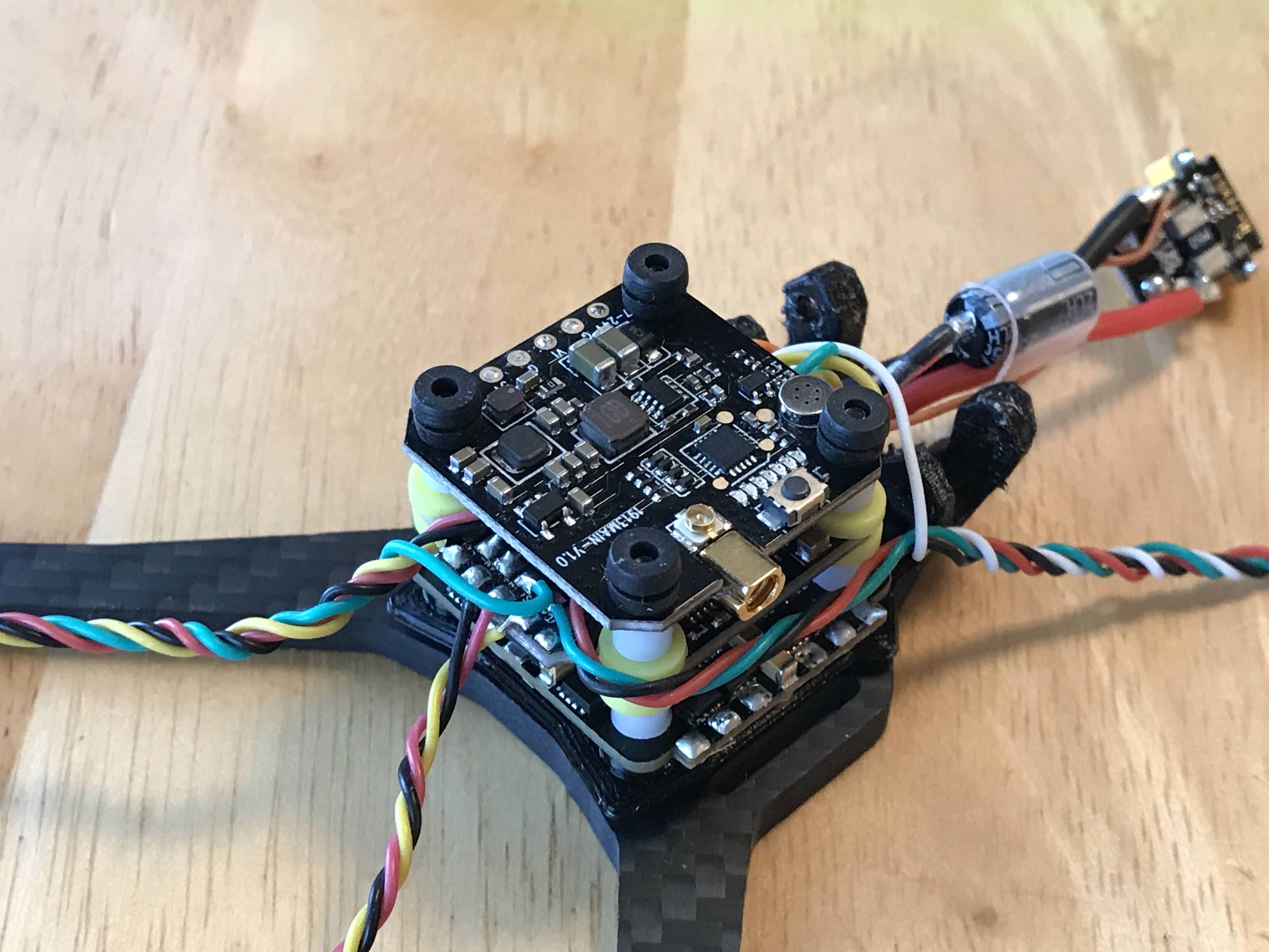
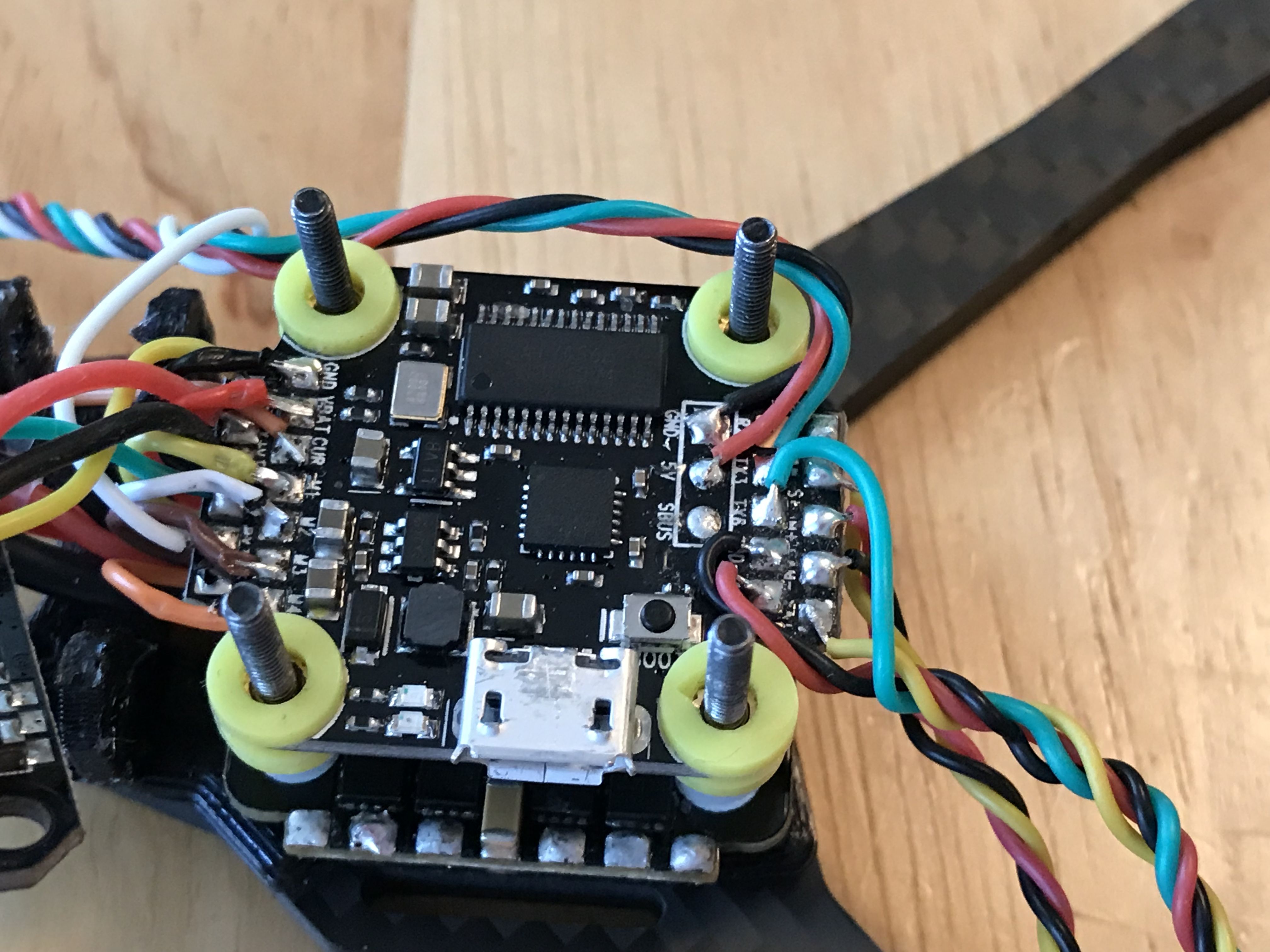
Flight Controller Assembly: Begin by soldering all of the harnesses you'll need. You should have a good idea from the dry-fit how long you should leave each harness. Start with any pads that will be covered up by other wires. Twist all wire harnesses to help reduce EMI. You can see from the pictures below how I routed the harnesses. For the VTX and the RX, it may be easier to solder on the wires directly and then trim them once you are more confident of the placement. Once the VTX soldering is complete, you can solder on the ESC harness wires. If you look carefully, you'll notice that ends of the sheaths are dimpled - use caution as the wires supplied are not silicone sheathed and will melt.. Once finished, install four (4) more nylon spacers onto the stack as shown in Step 3 of the Dry Fit.
-
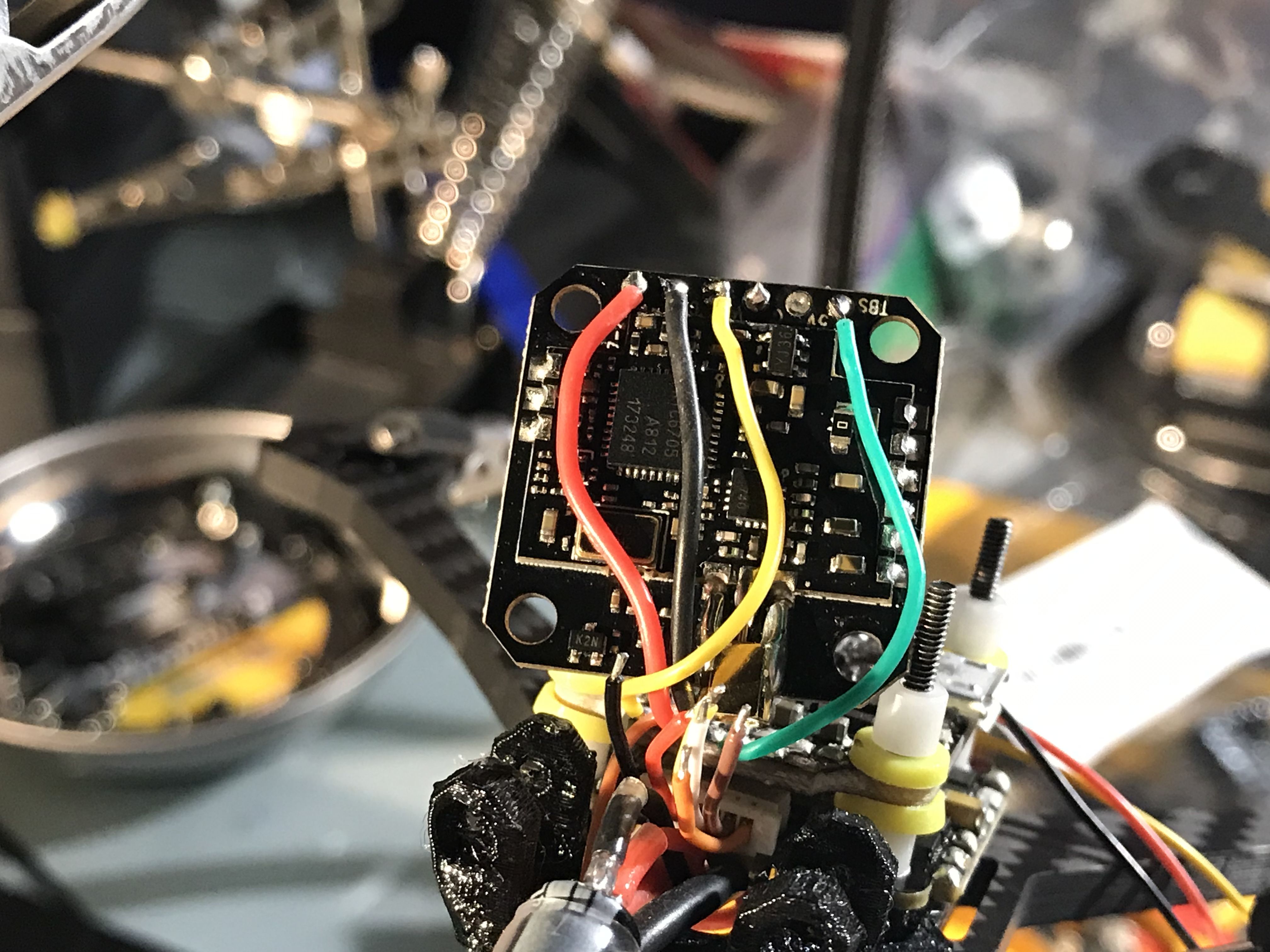
VTX Assembly: With the harness wires soldered to the VTX (See images below), orient the VTX so that the MMCX/UFL connectors are facing right (when looking at the front of the quad). UPDATE: I was having severe video noise issues when orienting the VTX this way. What I learned is that flipping the VTX 180degrees (selector button facing down toward the FC) solves the noise issue I was having. The pictures below do not reflect this Place the VTX onto the stack and install 20mm gummies over the VTX. If you don't have these, you can take four (4) of the white nylon standoffs and very carefully cut their length in half. Before installing the top plate, check to make sure that your stack screws are protruduing slightly below the bottom plate. This will allow you to thread into the lock-nuts in the top plate without overcompressing the stack. This is a great time to connect all the component harnesses and antenna's and do a quick video and control check. Go ahead and bind your RX too. It's OK if you haven't trimmed the RX harness to length yet, solder it up extra long and you can trim and resolder to length at the end. Once you're satisfied that everything is working that should be working (motors excluded at this time), proceed with the build. If something's wrong, stop now and fix it before everything gets too tight to work on or before you've zip-tied everything closed.
-
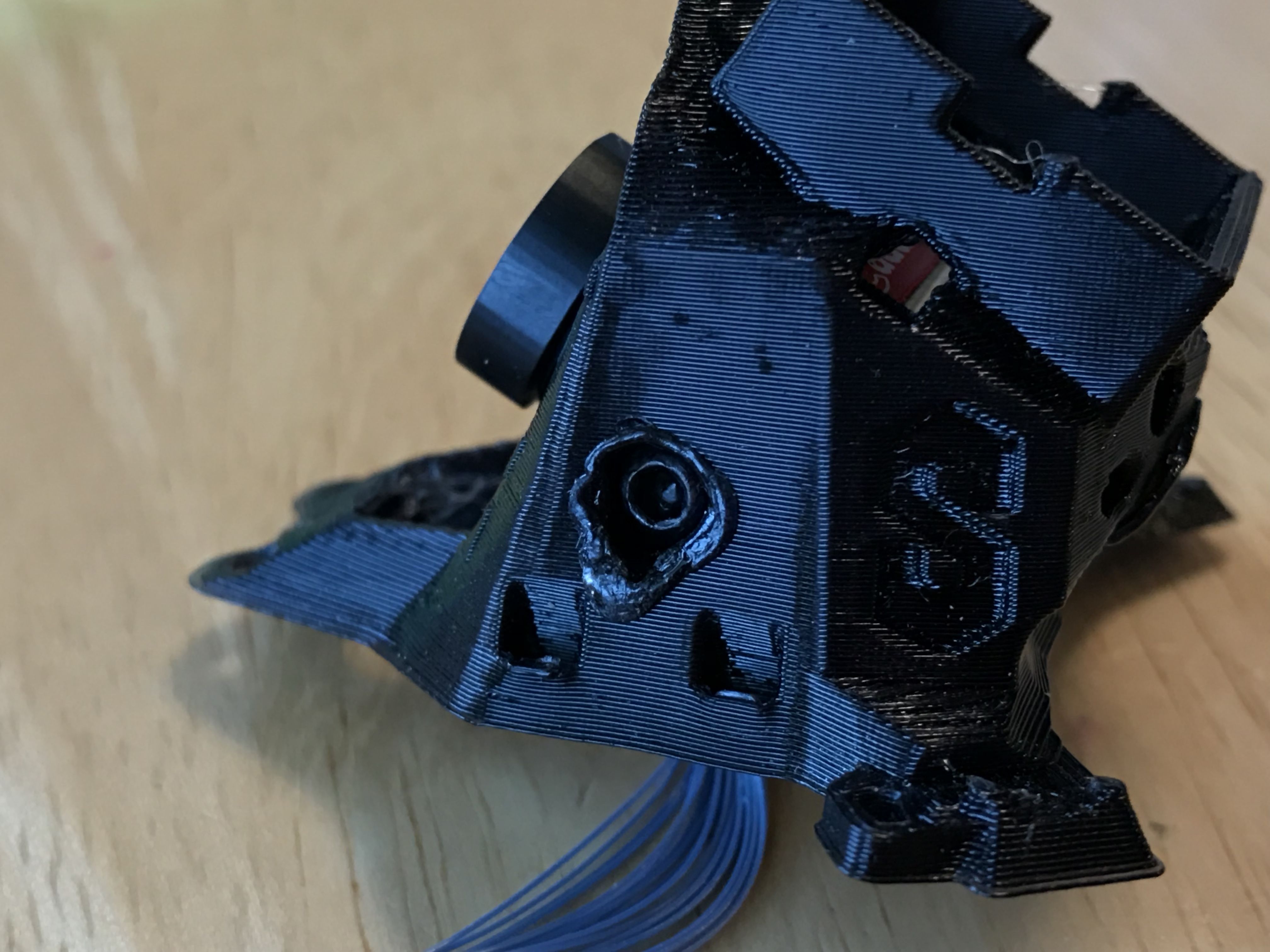
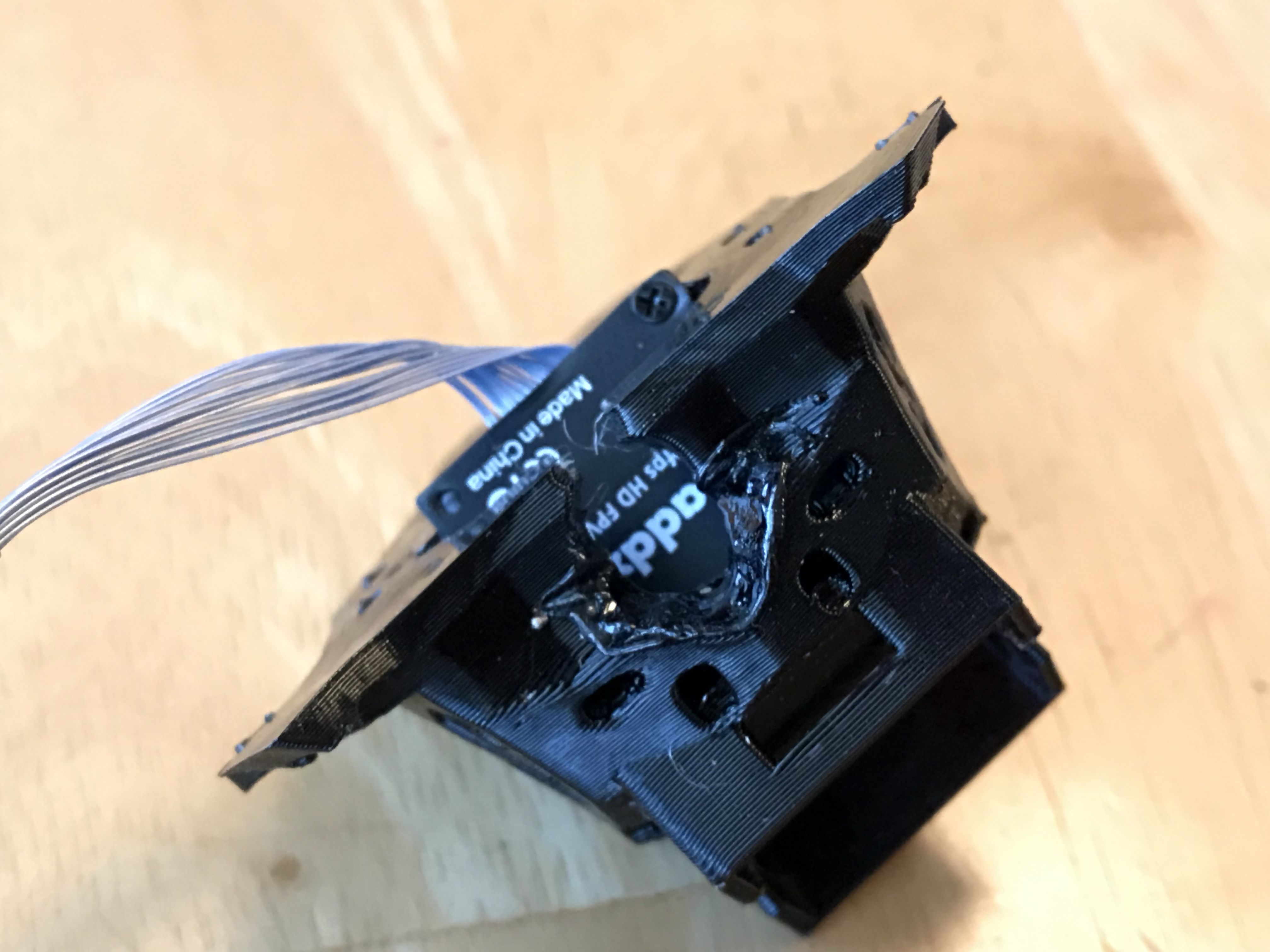
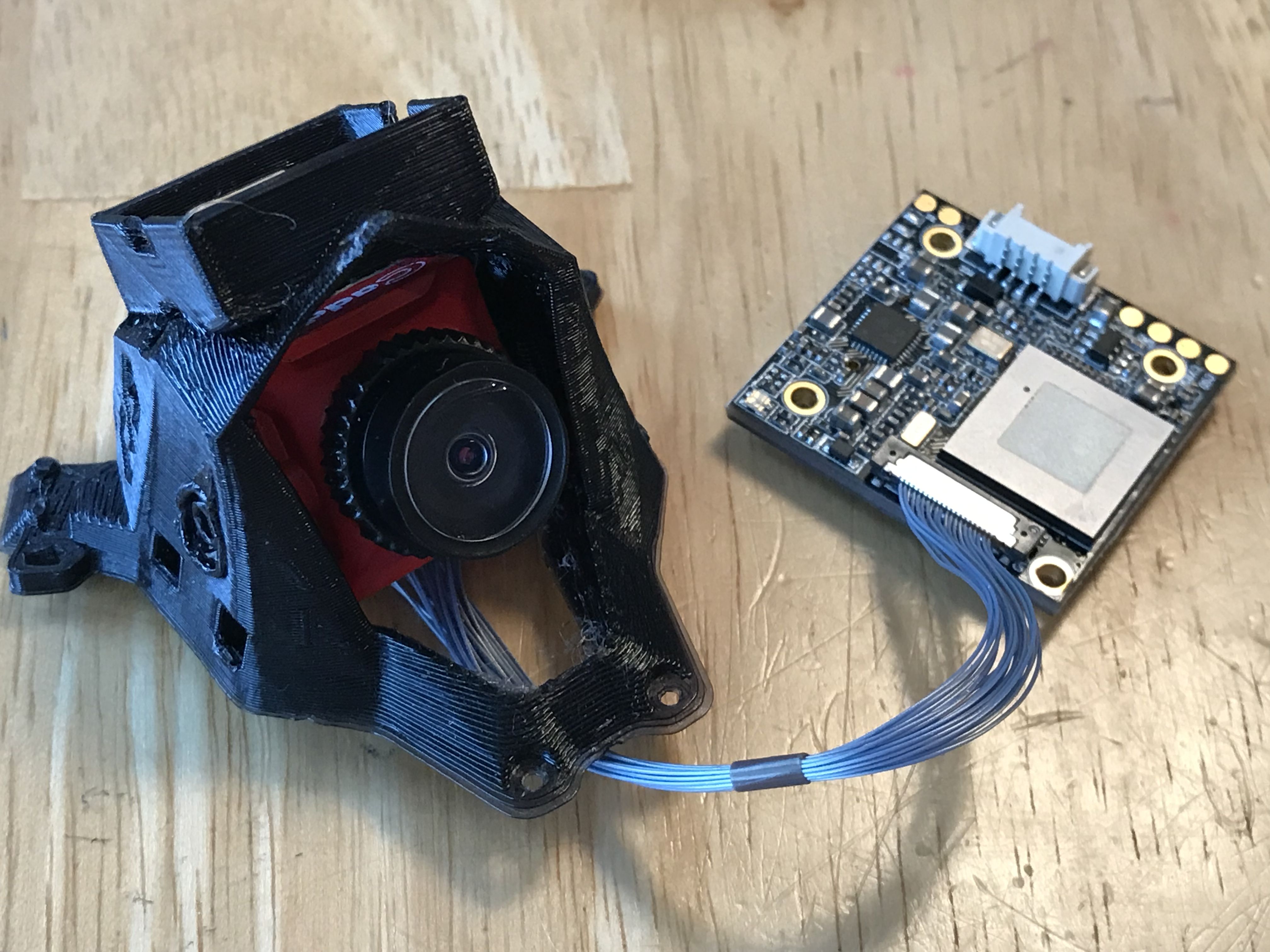
Camera Hood Assembly: For my particular build I went with the Caddx Turtle, which required a little bit of work to be performed on the TPU camera hood. Note: This is not a stock print with the RXSB, so if you want the camera hood you will need to print it or have it printed.. The screws supplied with the Turtle were too short for the thickness of the hood, and all I had available to me were 2mm cap-head screws, so I used the tip of my soldering iron to open up the counterbore in the hood. Simple enough and it allowed me to get the camera installed. See pictures below. You can go ahead and install the GPS antenna into the back of the hood and secure it with a zip-tie - there's a small port at the back of the GPS pocket for the harness to pass through. If you plan to install the immortal T antenna on the hood, go ahed and thread the coax through the back of the hood and use a zip tie to loosely hold it in place - you'll remove it later once you get everything placed where you want it and final-installed.
-
Top Plate Assembly: Place the four (4) M2 nuts into the counterbores of the top plate. They should fit with a little bit of force, though they may also slide in easily. For me, two were easy and two required a little coaxing. Place a drop of blue thread locker onto the threads of the nuts and prepare to place the top plate over the stack. If you need to thread any antenna coax cables or harness wires through the top plate, now is the time to do it. Carefully place the top plate onto the stack screws and, while holding the nuts in place with your finger, thread each screw into the nut until you begin to feel the screw against your finger. Stop and repeat for each screw in a criss-cross pattern. Once all 4 screws are in, tighten them down a little bit more, but not so much as to overcompress the stack. Check carefully for interference or contact. Use a multimeter to check for frame grounding or shorts across the XT30 pigtail.
-
Motor Assembly Pre-assembly: If you don't plan to install Racewire and/or RaceLightWire Mini's, skip ahead to step 9. I chose to use 2 racewire mini's for the front motors, and 2 racelightwire mini's for the rear motors. Tin all 6 pads on the racewire, and tin only the 6 motor pads on the racelightwire. Once you know what color you want to use for the LED's, solder bridge the correct pads to achieve that color. See https://tinysleds.com/products/rgb-racelitewire-mini-leds-2-pack for details on which pads to bridge. Place double-sided tape (I use the grey 3M version) on the backs of the PCB boards and trim any overhanging excess. Before removing the protective backing from the tape, place the PCB's onto the arms about where you want them, making sure to leave ample space for the motor wires without having to cut them too short. Once you're satisfied of their location, go ahead and remove the backing and place the PCB's into place. Skip to Step 10.
-
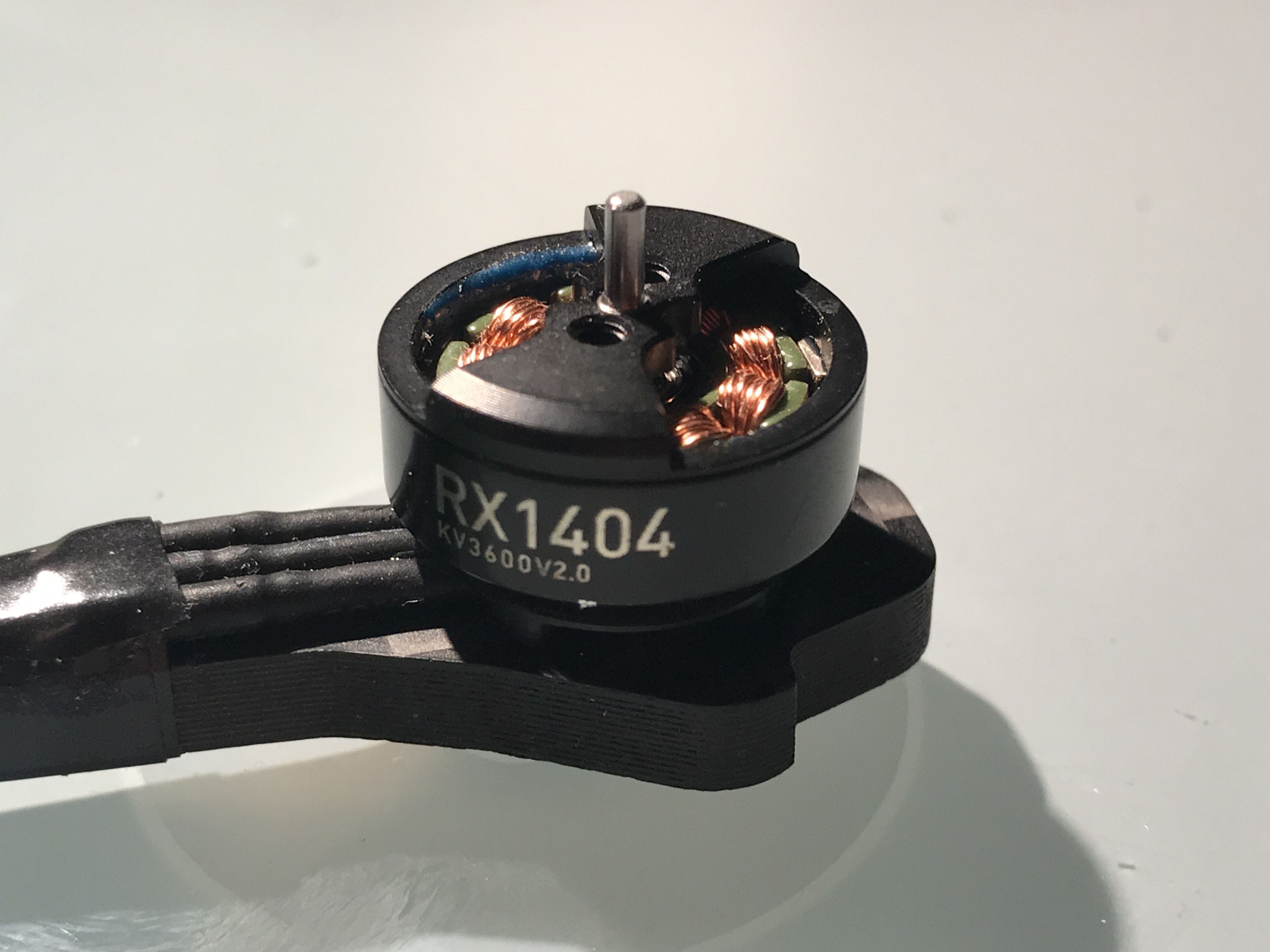
Motor Installation (no Racewire): Install each of the motors onto the arms, making sure to use a drop of blue thread locker on each of the screws. Check that that your screws are not too short or too long prior to installation. Tighten each motor to suit, but remember that these are M2 screws, so don't go crazy. Route the motor wires along the arms toward the ESC - you may want to put a loose zip tie or e-tape gently to hold them in place while you measure them for installed length. Take note of where each wire should be cut to meet the ESC pads, then trim and tin the leads. Solder the wires into place with care, but there should be enough room to to get a tweezer and chisel tip in for the joint.
-
Motor Installation (with Racewire): Install each of the motors onto the arms, making sure to use a drop of blue thread locker on each of the screws. Check that that your screws are not too short or too long prior to installation. Tighten each motor to suit, but remember that these are M2 screws, so don't go crazy. Route the motor wires along the arms toward the racewire or LED, and trim the wires at the PCB. Save the excess for the other side. Solder each motor wire to the PCB or LED. Check for bridged joints with a multimeter. With the trimmed motor wire, tin the ends of the wires and attach them to the twelve (12) motor tabs of the ESC. Once complete, route each wire individually to it's respective PCB or LED board, trim to length, then solder the wire to the board. Repeat for each wire. Check for bridged joints or ground issues with a multimeter at each PCB and at the XT30.
-
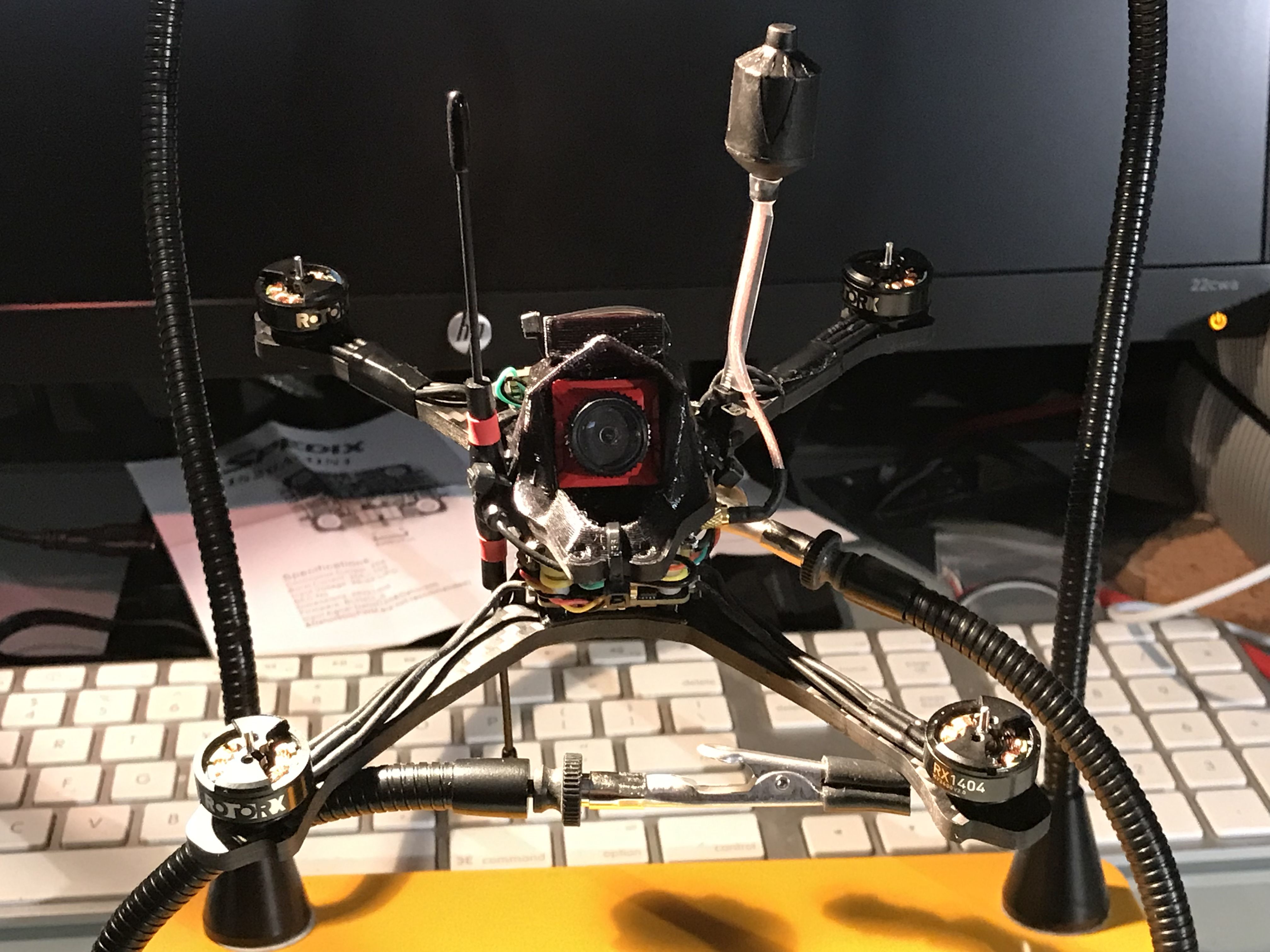
Camera Hood Installation: Place the camera hood that was assembled in step 6 onto the top plate. Check for any clearance issues and adjust accordingly. I chose to place the crossfire nano RX onto the back of the camera and I routed the immortal T down through the top-place hole for a vertical orientation. If you choose to use the horizontal orientation, you may have to double-back on the UFL coax. Now is when you trim your RX wires to length and solder them to the RX. Once you're satisfied that everything is in place as desired, begin running zip-ties through the holes on the canopy and around the top plate. Cinch everything up tightly and trim any tails you don't plan on using for antenna mounting.
-
HD Board Mounting: It turns out that the Turlte is an absolute PITA to install on this build, but it can be done. Take a look at the pictures below for cues on orientation assembly, but suffice it to say that the SD card slot needs to be visible from the rear, and oriented horizontally to the right (when looking at the rear of the quad). Install two (2) M2 vibration standoffs into the inner ears of the TPU backpack pad that was first installed in Step 1 of the dry-fit. Fully seat them against the TPU. Place the Turtle PCB board into the gap between the outer ear and the M2 standoff just installed, and thread an M2 cap-head screw into place. You will have to install one (1) first, then force the other one into place. With a pair of needle-nose pliers, hole the vibration standoff while you tighten the screw. Don't overtighten, as you can rip the M2 standoff. Using the existing zip-ties that are over the rear arms of the camera hood, run another zip-tie behind the Turtle board and through the previously installed zipties. Close the loop to secure the Turtle board against the frame, taking care that no harness wires get pinched. Snug up the board, but dont' overtighten it.
-
Final Checks: You should know this by now, but in case you don't, don't go slapping a battery on your quad before you do some basic checks. 1) Have you set your failsafes? 2) Have you don't a continuity check on the XT30 after everything is complete? 3) Do you have a smoke-stopper (if not, get one, they're super cheap)? 4) Did everything bind and operate correctly in Step 5? 5) Did you set up betaflight and your radio for all of the switches and control functions? If you can answer Yes to the questions above, turn on your radio, plug in the smoke stopper, and install a battery. Do a quick arm (props off!!!!) and use your finger to check against the motor bells for orientation. Also check that Motor 1 spins Motor 1, etc, in Betaflight. Make any adjustments in BlHeli Suite and/or the Betaflight Gui.
- Go have fun!
Maiden Flight:
Photos


Part List
Show stores (9)Guides & Reviews
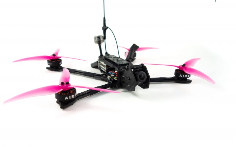
AirbladeUAV has done it again and this time they've brought long range to the 5" class! Based on the popular Transformer Mini, the new Transformer 5" Ultralight adopts a lot of the same design philosophies with larger props and more payload capacity. It can fly upwards of 20 minutes on a 4 cell Li-Ion battery pack and in ideal conditions it's got a range of over 4 to 5 miles. In this guide I'll walk..
Read more
With the release of the DJI FPV Drone cinematic FPV has become a lot more accessible, but you certainly don't want to crash a $750 drone! The QAV-CINE Freybott is a compact, lightweight cinematic FPV drone that can take a hit and keep going. It's a lot safer to fly indoors and around people. With a naked GoPro or the SMO 4k you can capture some great stabilized footage. In this guide I'll show you..
Read more


Nice and informative build guide, how do you like the cl racing f4 mini?
So far so good. Seems stable enough.