
Hello,
The skystar kit is an easy to intermediate build containing everything you need except the radio receiver the battery and the tools to mount it.
It flies 'OK' compared to 5 inch quads I am used to fly.
It does not like quick and sudden maneuvers. 1 out of three times it will do something funny like an oscillation but not something that will cause a crash. It will however limit your apetite for acro.
Where it shines is for cruising and taking altitude. It takes altitude with no effort, at low sticks, without making noise. Speaking of which, the sound it makes is pretty cool compared to how 5 inches scream.
If i had to summarize it in one sentence, the skystar is "a quad for granpa"
This is my 3rd build posted on rotorbuilds.com
This is a kit assembly not a personal selection of parts.
Since I found no instruction manual on the web I thought it would be helpful for someone.
This is the link on Gearbest where you can find it KIT at 170$ on promotion https://www.gearbest.com/brush-fpv-racer/pp_009300853471.html?wid=1433363#goodsDetail. For some reason I get an error when I put this link on rotorbuild so I put the Banggood instead currently at 190$.
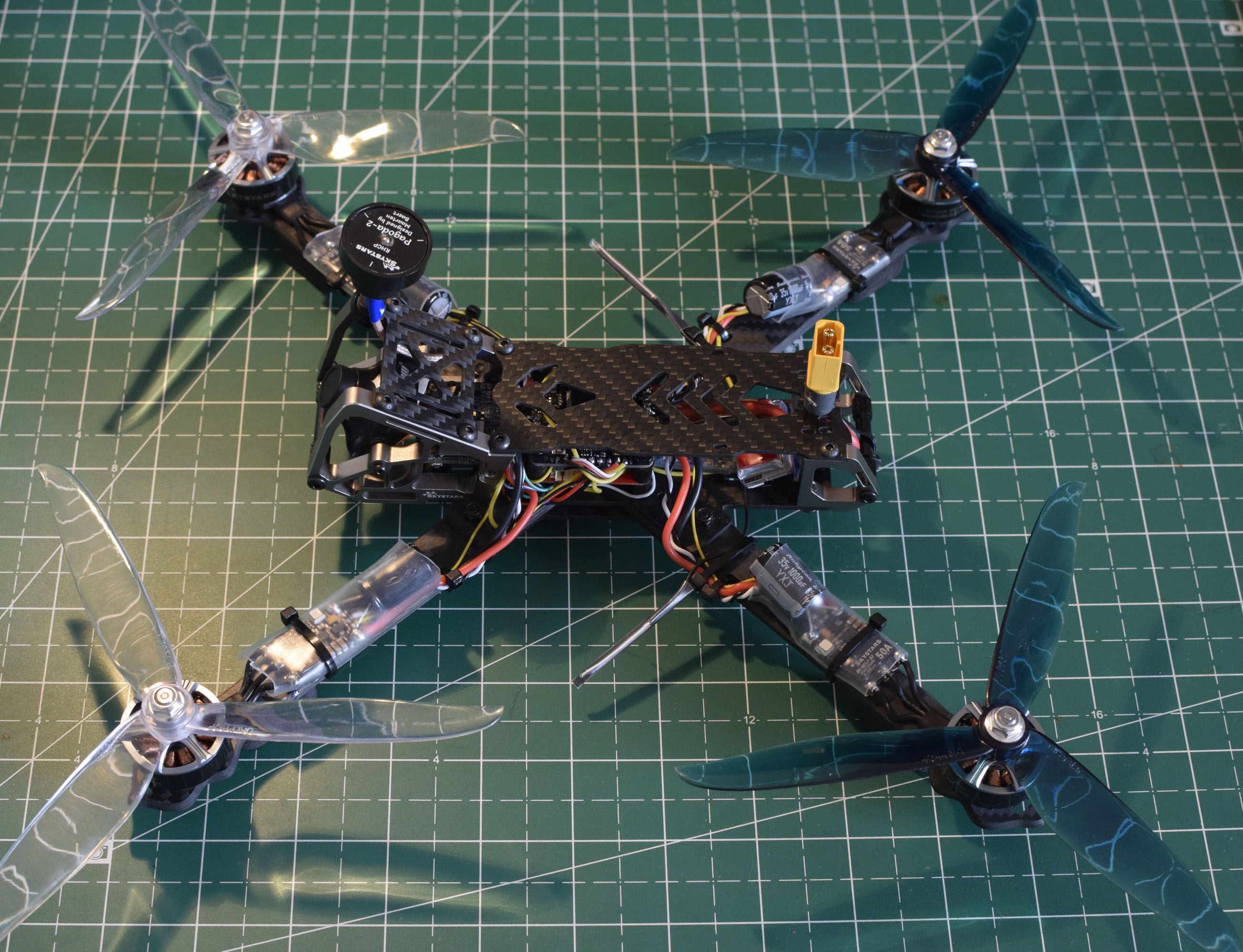
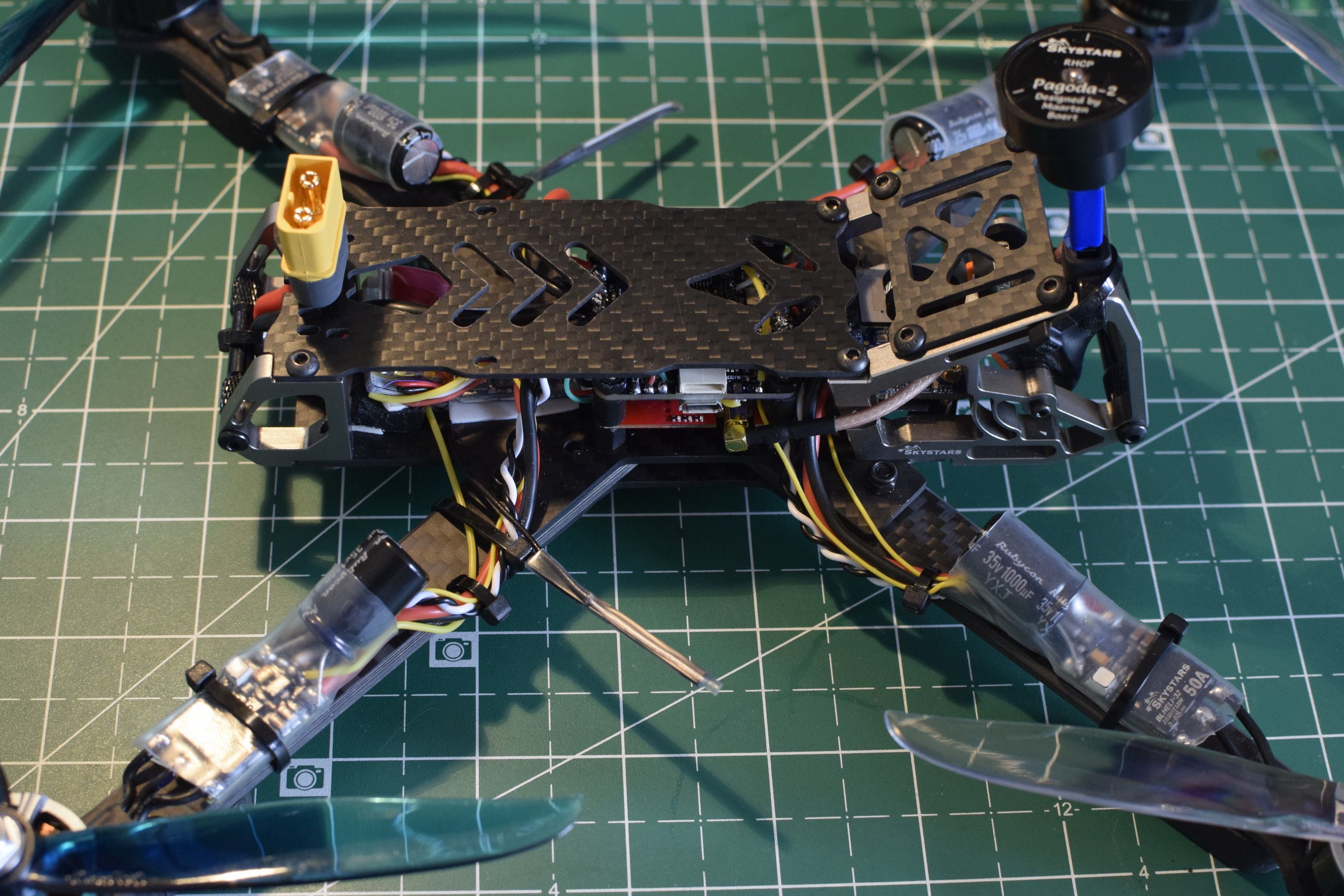
Assembling the frame
Very straightforward if you do the same as in the pictures.
Note the 4 rubber standoffs not included in the kit. They are used to reduce vibrations.
If you are using the normal nylon, you will put the red VTX (Video Transmitter) on top of the FC (Flight Controller) to help dissipate more heat.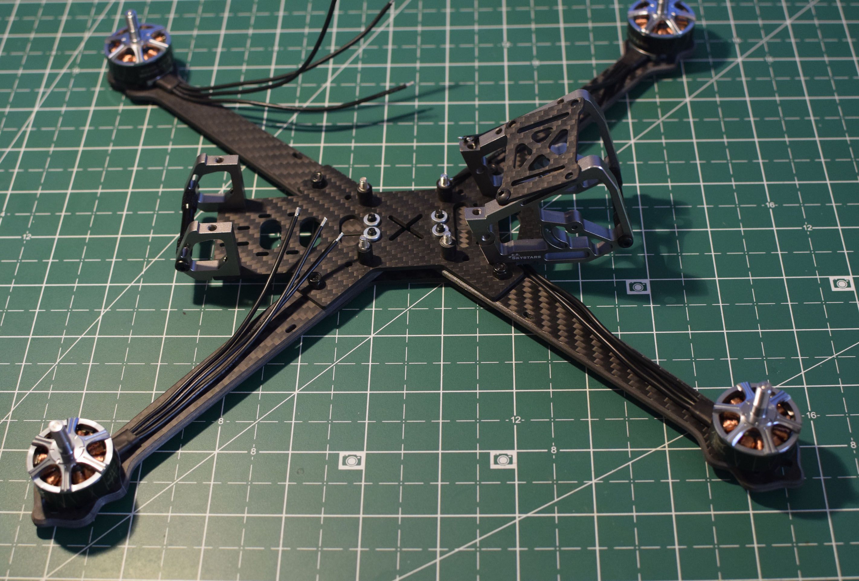
The rubber standoffs are less efficient with more weight, hence my choice of putting the VTX below the FC.
I use the command set vtx_low_power_disarm = ON so that the VTX is on low power when the quad is not armed.
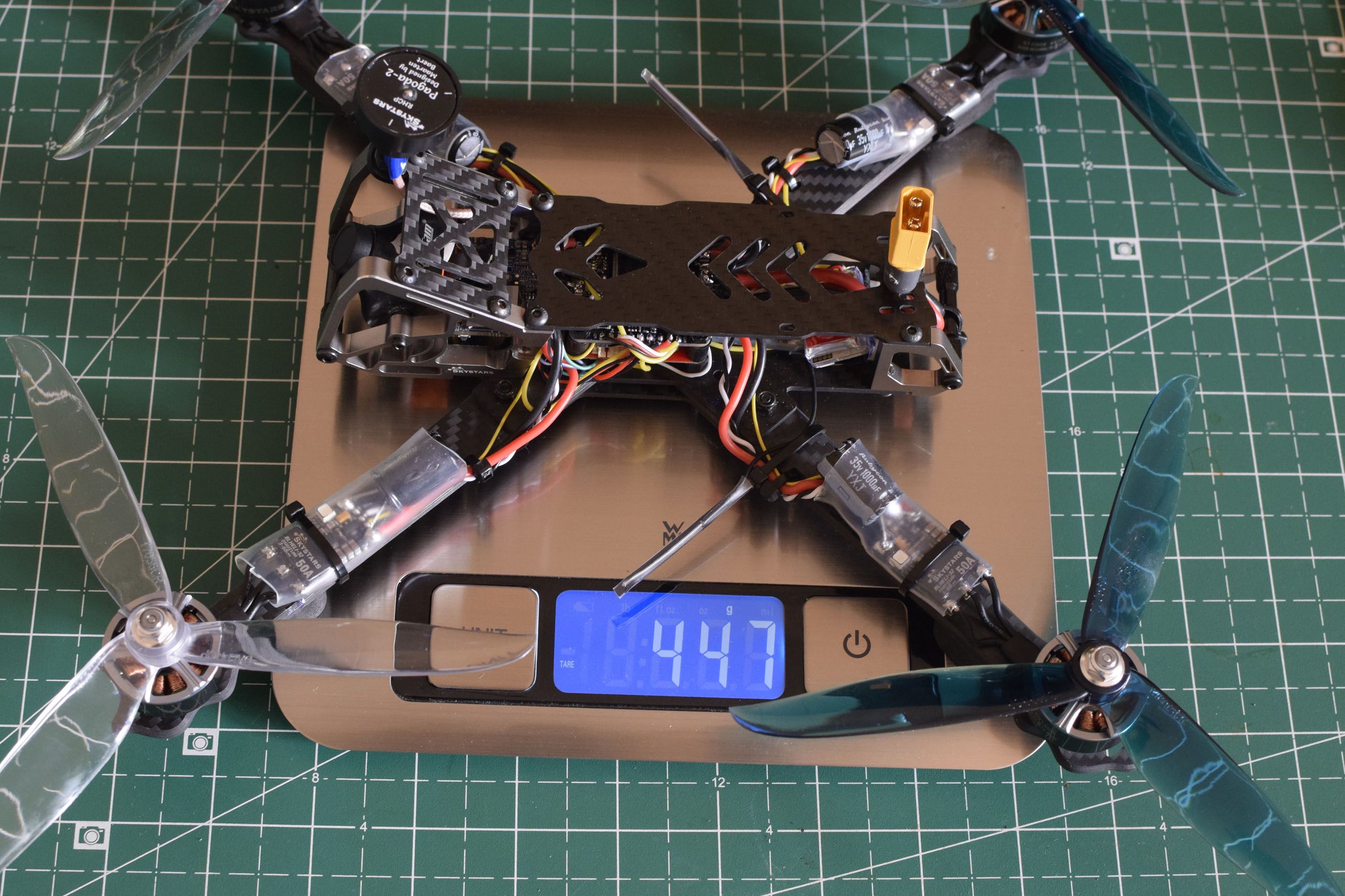
The fully assembled frame weighs 161 grams. The arms are a little bit too flexible in my opinion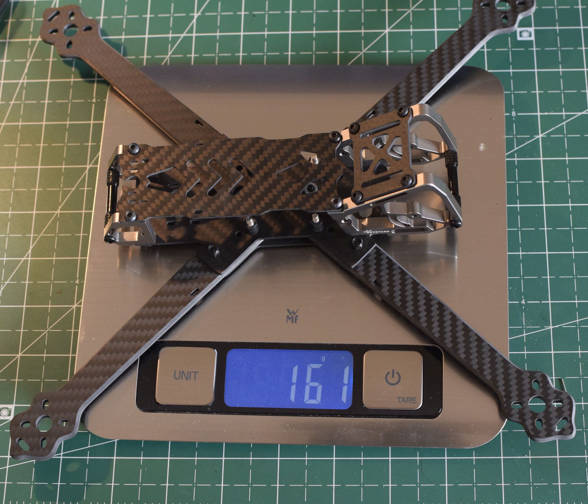
A note before you go on
Most builds are either from the 'inside out' (meaning start with the central stack and keep building until you get to the motors) or from the 'outside in'.
In this build I tried a different approach : I soldered component after component and tested everything works fine everytime I added something.
At the end there was no surprise and everthing worked fine. It made debugging a lot easier, and in case of a mistake I would not burn all components of the build but only the one already soldered.
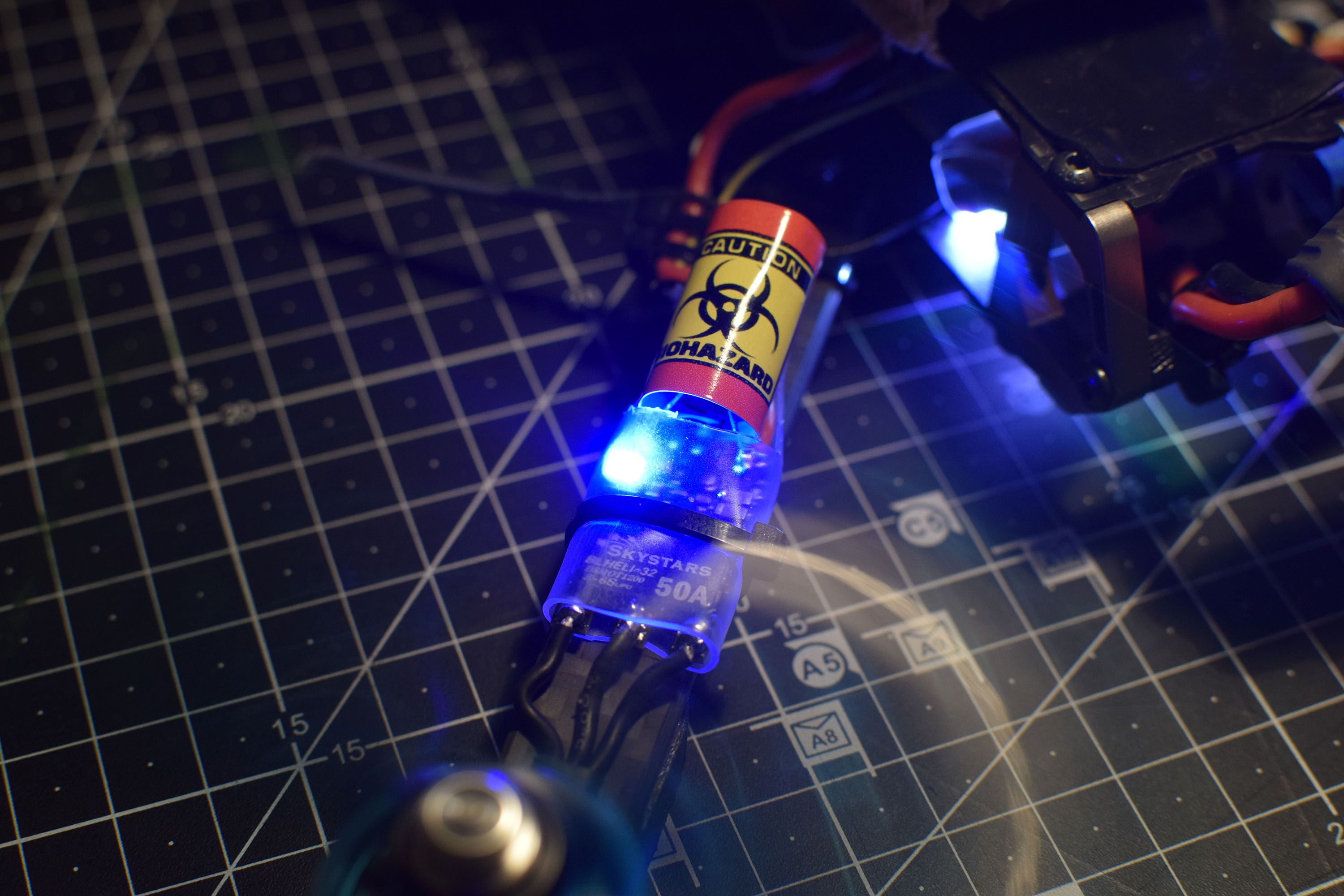
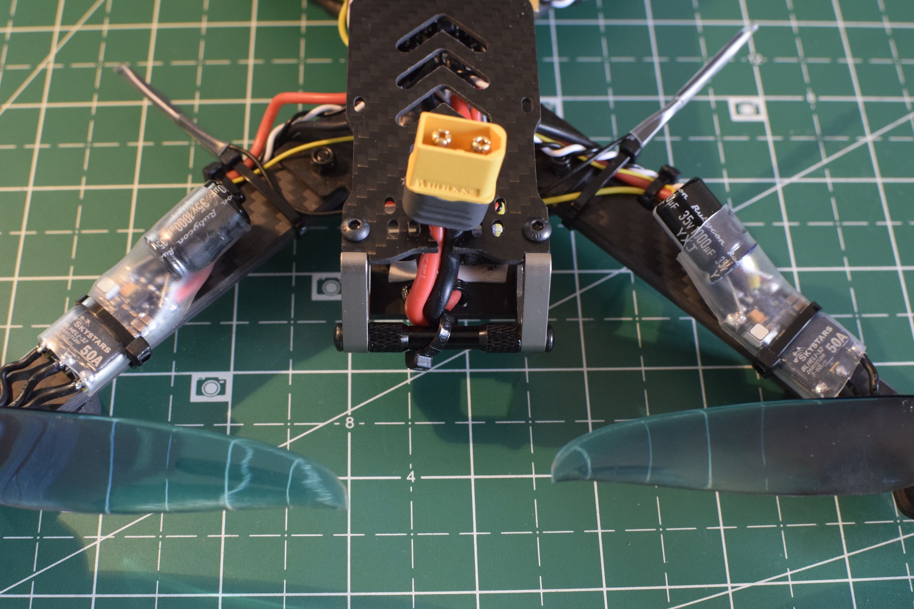
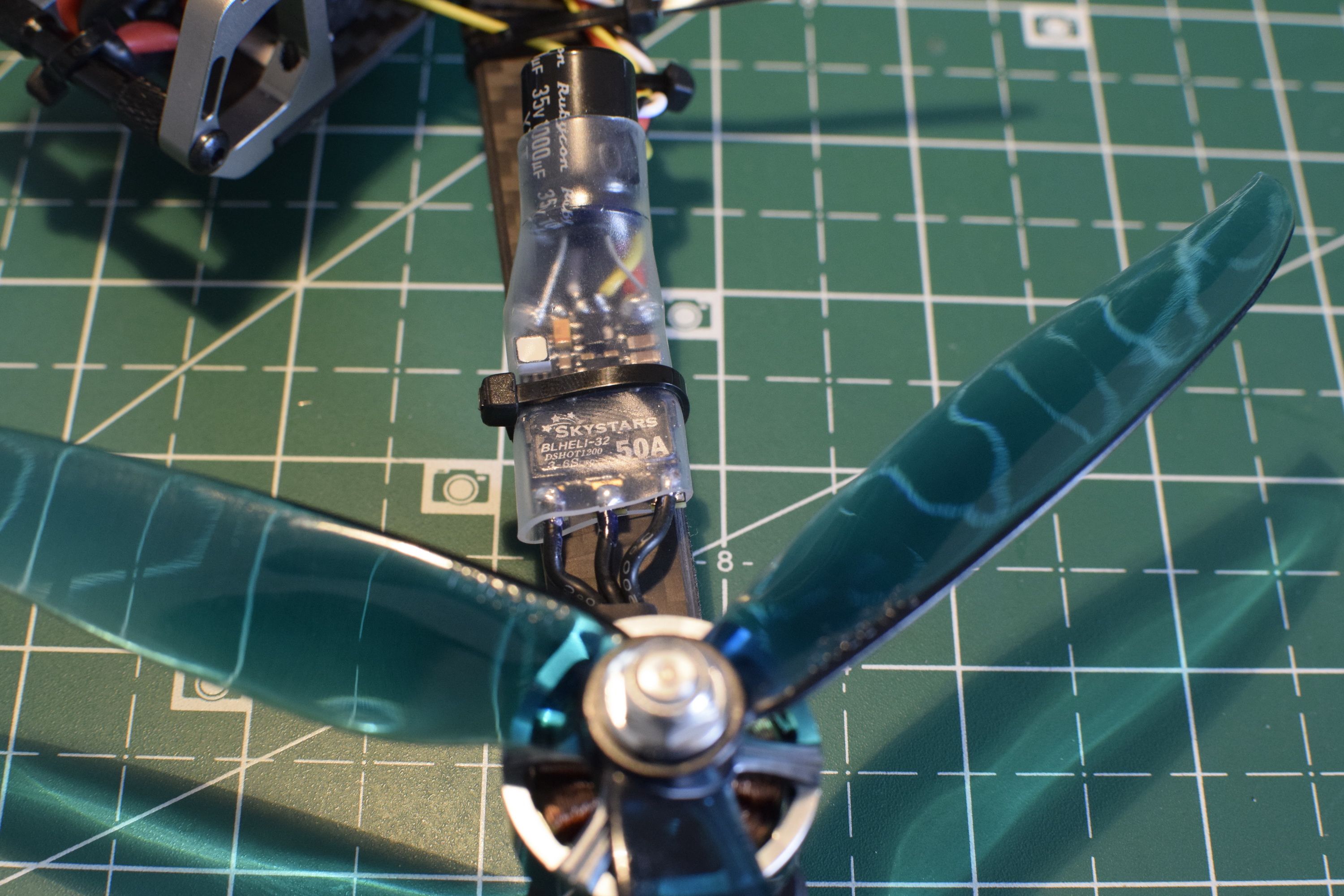
Prepare the ESCs
You will need to take off the transparent heat shrink IF you want to solder 4 X capacitor and the telemetry.
The ESC are pretty small for 50A and the FET used are the small kind. Although I don't have an oscilloscope to verify it, I suspect these ESC will generate a lot of noise. On my other builds I only use one capacitor.
The alternative is no ESC telemetry and a capacitor on the FC if you dont want to take off the prefitted transparent heatshrinks.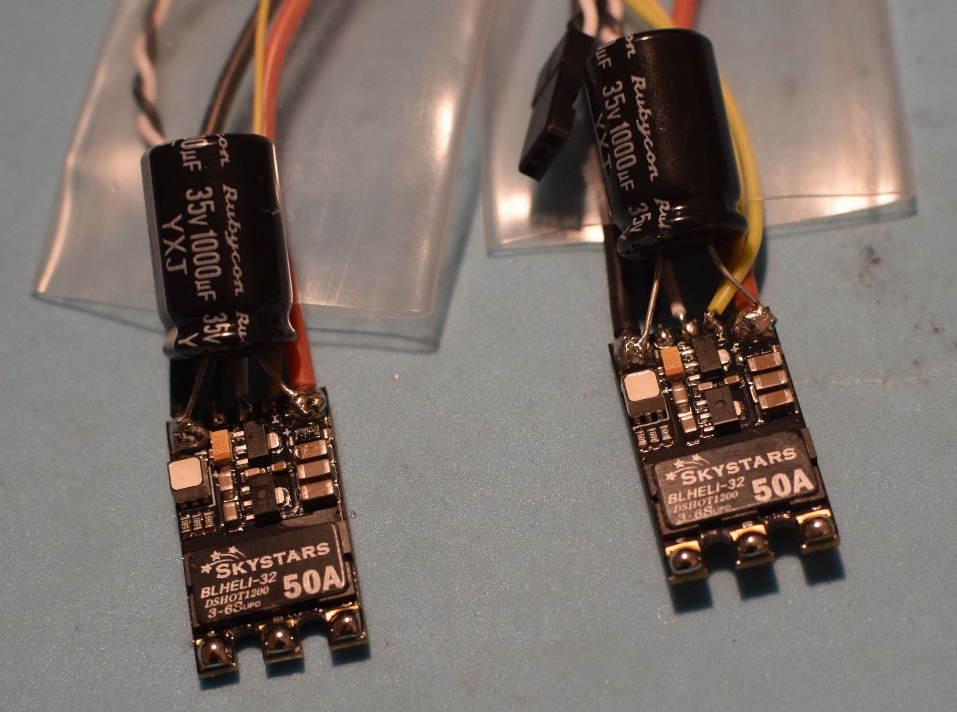
Note the 2 X ESC to ESC yellow wires and the yellow 2 X ESC to FC wires, this avoids to end up having 4 X wires to solder on the same pad of the FC UART RX
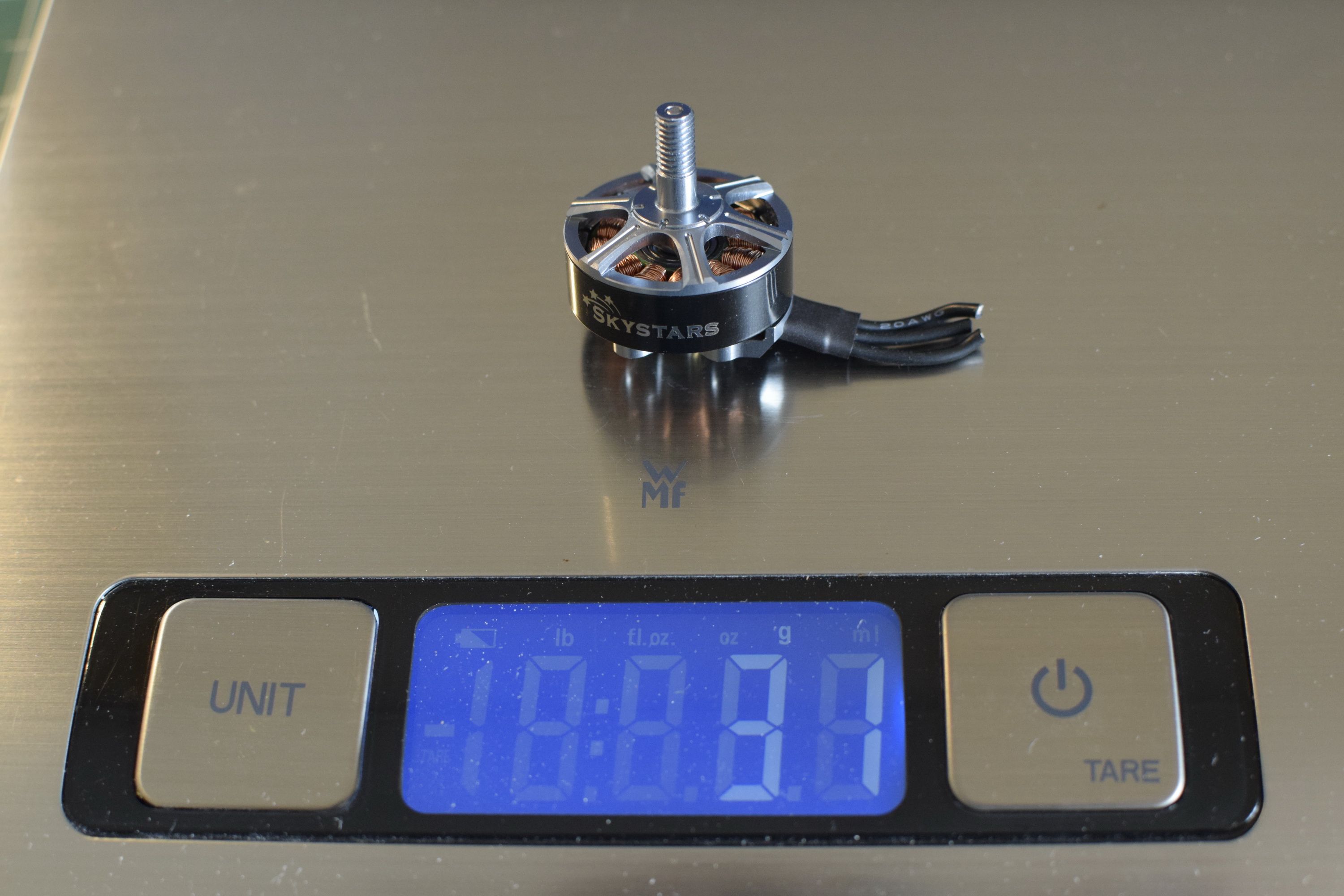
Prepare the Motors
Make your adjustments on the frame with a motor and an ESC and decide how long you want the wires of the motors.
I decided to have the ESC closer to the motor.
- Advantage : the propeller will never strike the ESC during a crash
- Disadvantage : the mass is further from the CG (centre of gravity) this means the quad will be less agile
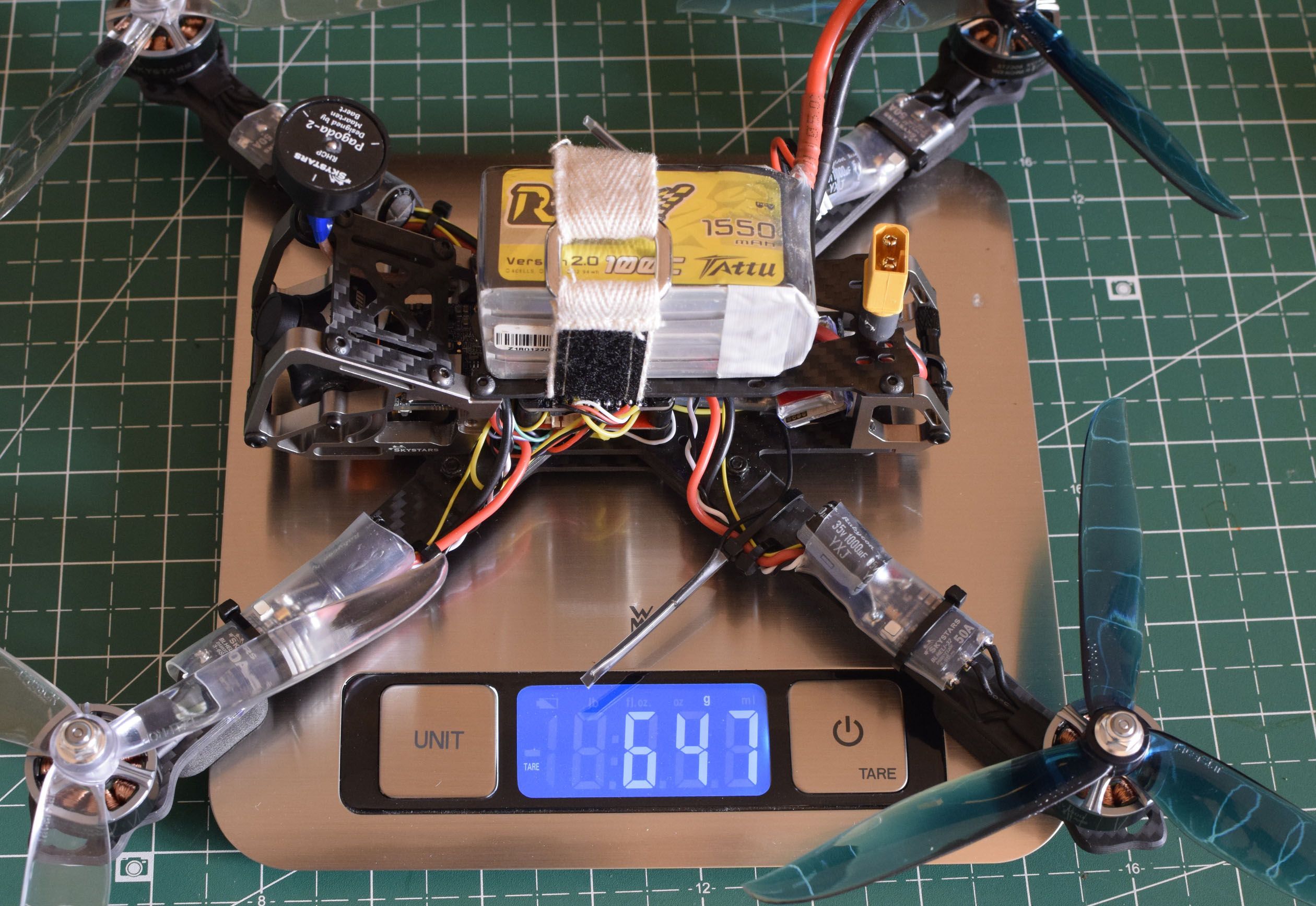
Each motor weighs 31 gram
Solder the lower part of the Flight Controller
The detailed Flight controller can be found on this link
https://www.rcgroups.com/forums/showpost.php?p=40556675&postcount=55
Thank you GCRC !!
Before you do any soldering, you might want to plug a USB cable and check that your FC is working properly with Betaflight.
Next solder the XT60 Lipo connector and plug a Lipo with a 'smoke stopper' if you have one.
The Leds on the FC should turn red and green.
Next prepare the UARTS 3 and 6 for soldering (on top right of below picture).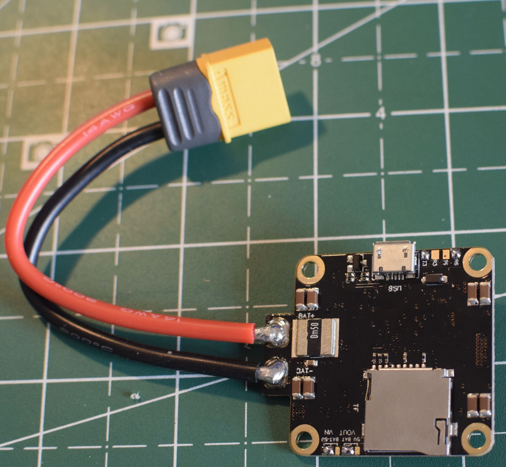
Next you need to choose the VTX voltage and the FPV camera voltage. (on bottom left of below picture).
- I went for Battery voltage for VTX called VOUT on the FC
- I went for 5V for camera called VIN on the FC
the idea is to bridge with solder the middle pin with the battery pad or the 5v pad.
If you have a multimeter, plug a LIPO on the FC and check on the other side of the FC that the voltages for Camera and VTX are correct.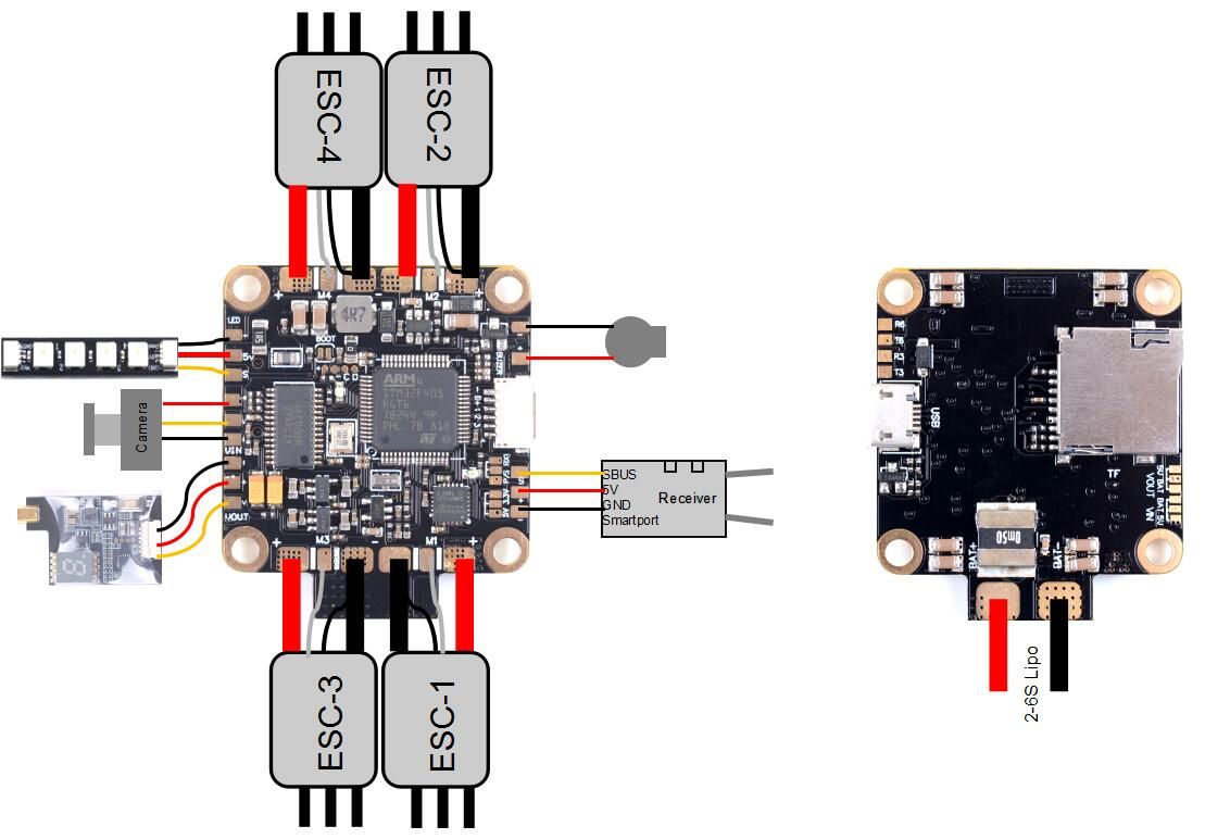
Solder the FPV camera and the VTX
Solder using previous diagram.
This should be very straighforward if you use the provided runcam swift V2 provided in the kit.
I personally went for a Runcam split mini 2 to have HD footage without carrying the weight of a gopro and without the stress of fearing to lose my gropro in a long range crash.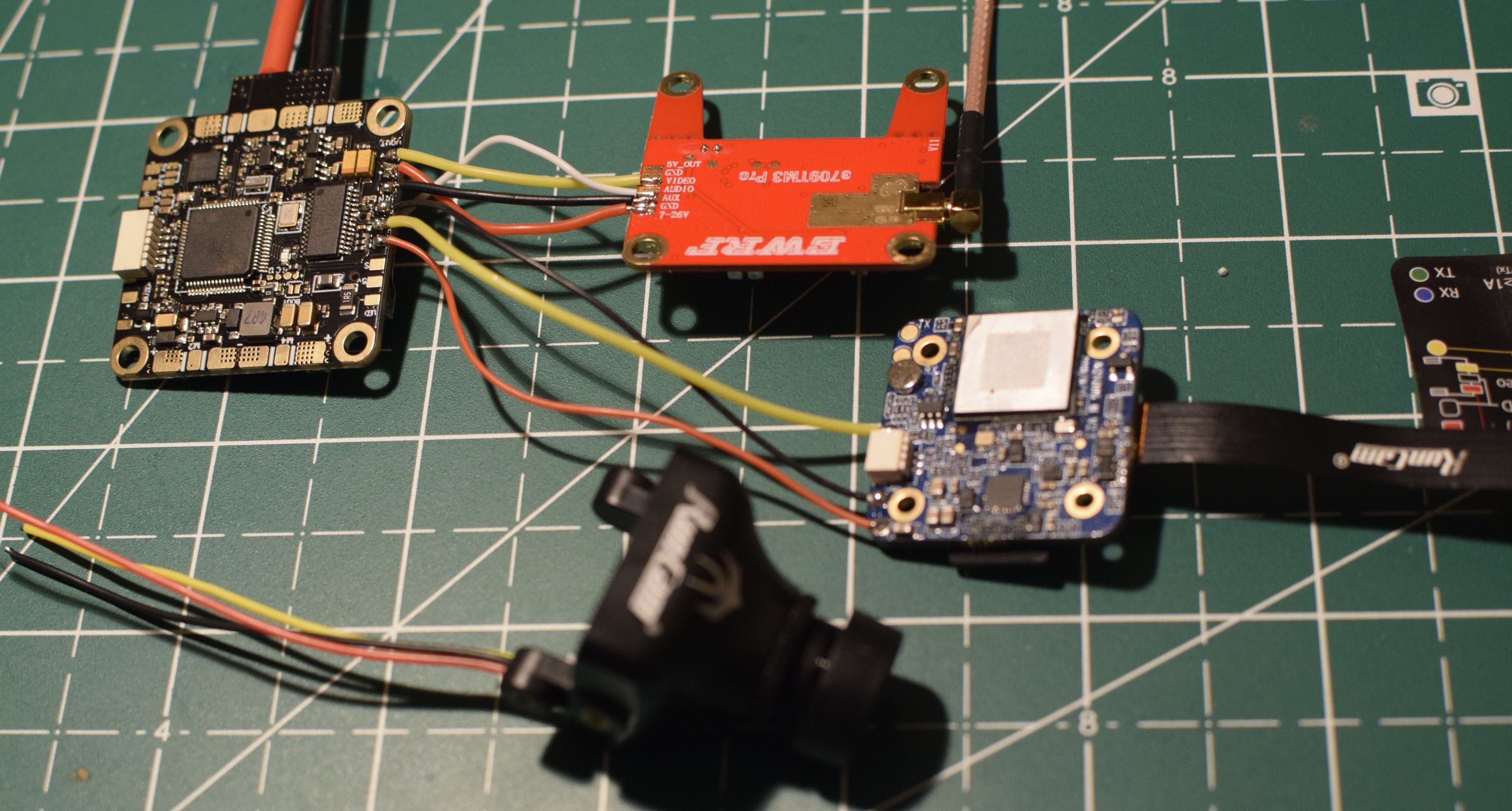
From now on make sure you Plug the VTX antenna everytime you plug a LIPO. I won't remind you in the remainder of the build.
Plug a LIPO and check with your goggles that camera and VTX are working as expected.
Take a decision with your UART
This FC is limited to 2 UARTS so you can choose 2 of the below
- ESC telemetry
- Telemetry of the receiver (also known as smart port for frsky)
- Runcam
- Smart Audio or Tramp
- GPS
In my case I will go for the last two : GPS because I want to try long range and GPS might save my quad if I lose signal with the quad, and Smart Audio so that my VTX runs at full power only when the quad is armed
For mayden I wired ESC telemetry to make sure everything is running smoothly and Runcam to learn how it works.
Solder your receiver
I did not solder my receiver at this stage so no picture is provided but in your case, now is probably a good time to plug your receiver. Depending on your receiver you should bridge as per below diagam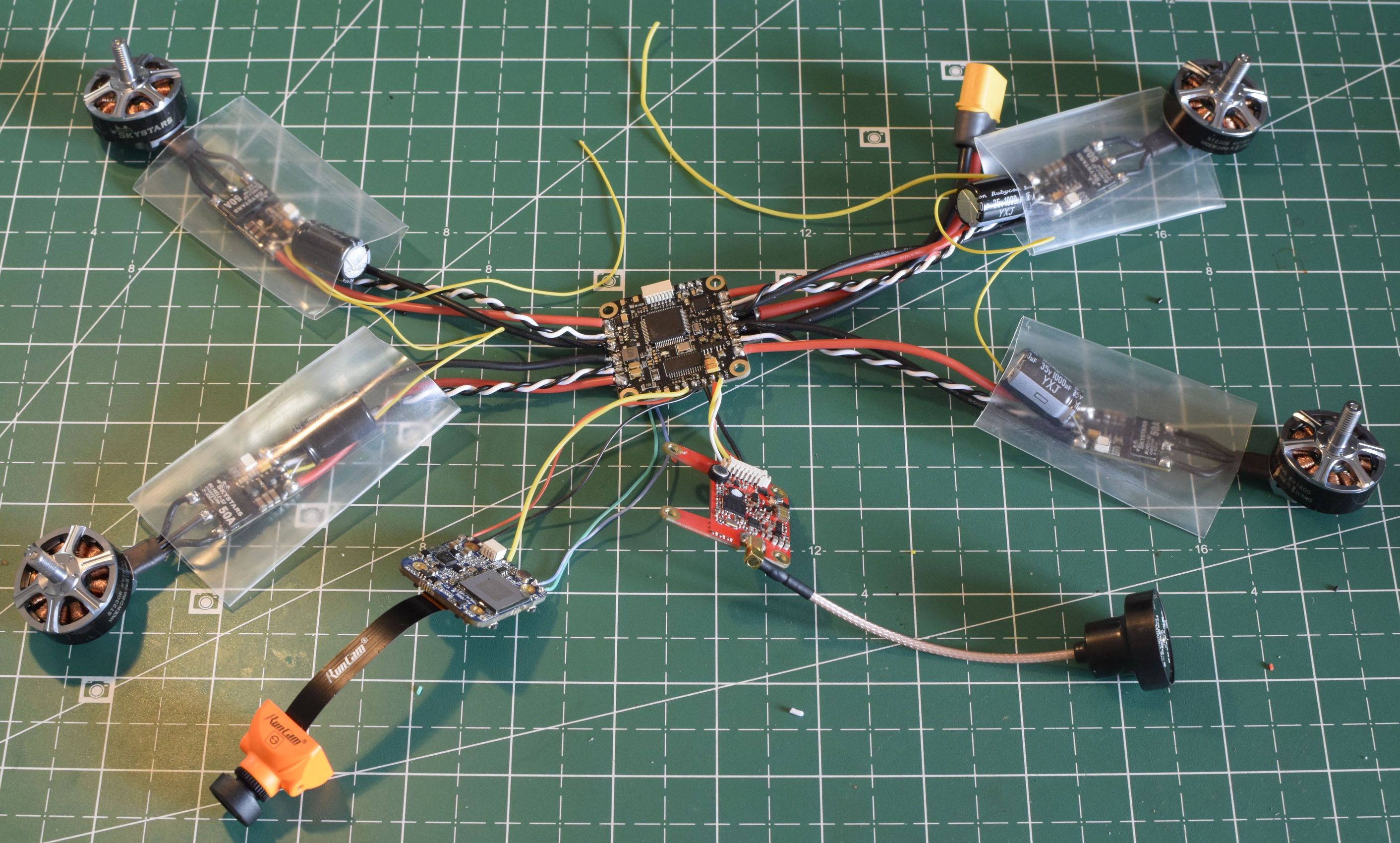
I used an XSR, so I bridged on 5V and on P/S
Bind the receiver and check that is recognized in Betaflight.
Solder the motors and ESC
Solder 3 wires ESC to Motor
Solder the white ESC wire on the FC first
Solder ESC to FC the positive and negative thick wires second.
Solder the thin black wire on the top of the thick one (can be tricky and or messy... hopefuly not frustrating)
Eventually solder telemetry on a RX UART pad located on the lower face of the FC
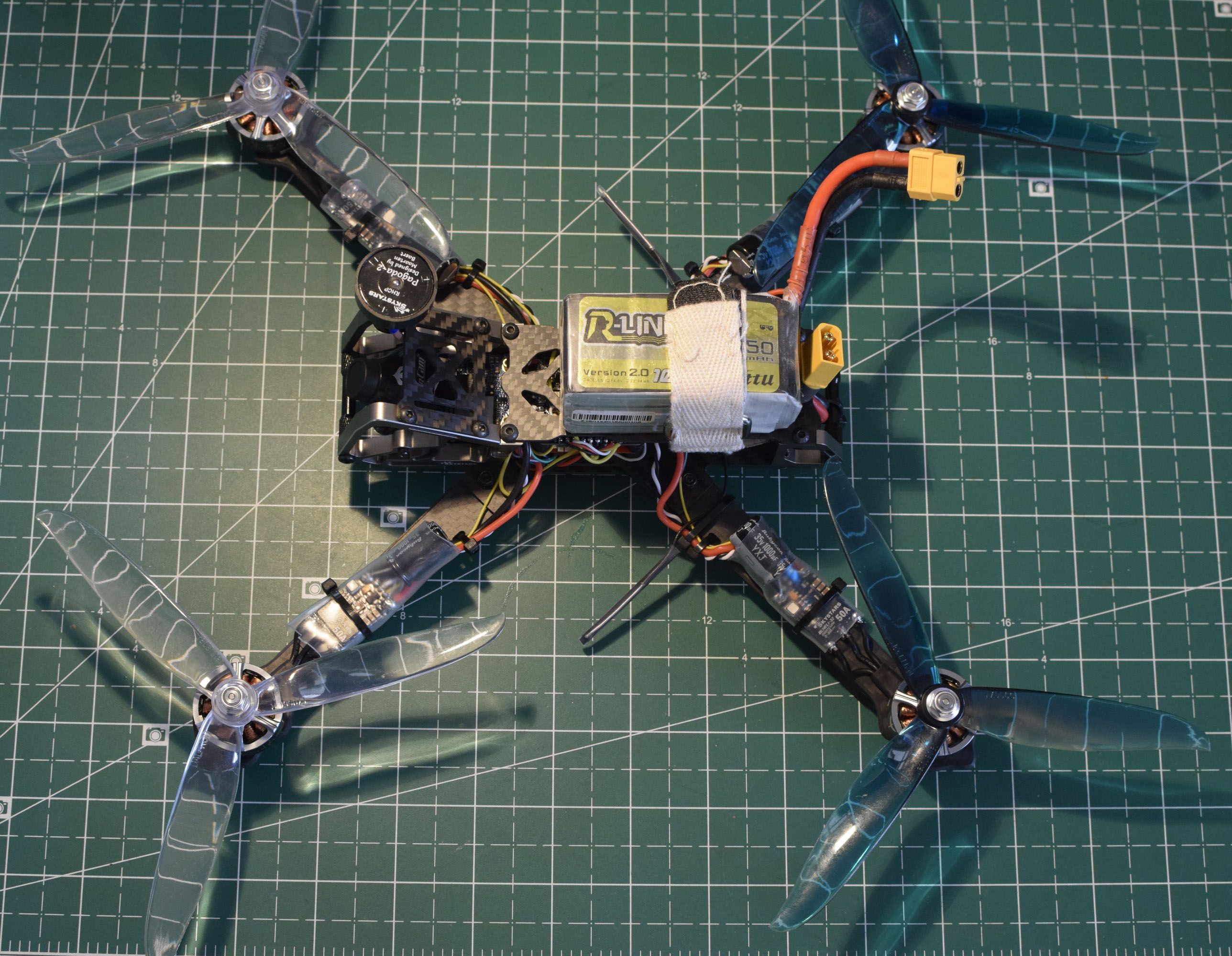
You should end up with a 'spider' like this.
Mount the 'spider' on the frame
This will allow you to check wire lengths are OK. If not make the necessary adjustments.
Only put one screw per motor for this stage. It's pretty cool to be able to hold your build without fearing of ripping a cable.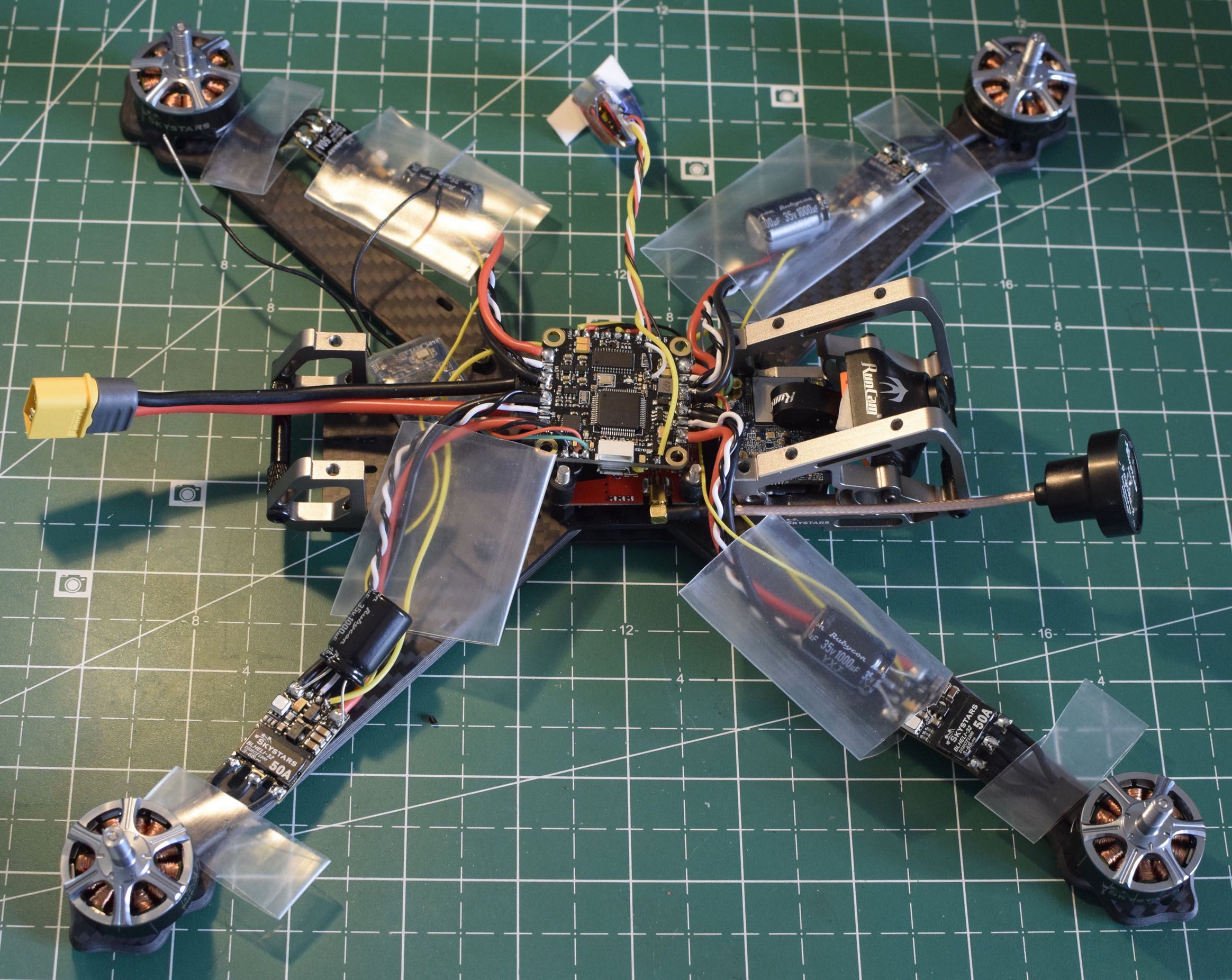
If all is fine, secure all 16 screws on motors. Personlly I didn't like the provided motor screws, I found them too short.
If you use longer screws makes sure they dont touch the motor windings (copper wire) or you will burn a motor (in theory).
In practice what you will burn is the tip of the carbon arm, which is exactly what happenned to me on mayden flight.
Acrews should not even touch the isolated black wire. If you have no idea what I am talking about, use the provided screws in the kit.
A special note about the runcam split mini 2
This only applies if you install a runcam split mini 2 (not provided in the kit)
It is not as straightforward as the rest of the kit.
You will need to file the aluminum cage that protects the camera in order for the mini stack to fit.
You wont be able to access the SD card without unmounting the aluminum cage.
In case you tried another way and it was better then what I did, please share it in the comment.
One alternative is to use double sided tape and put the mini stack on top of the FC.
Below are close pictures of what I did.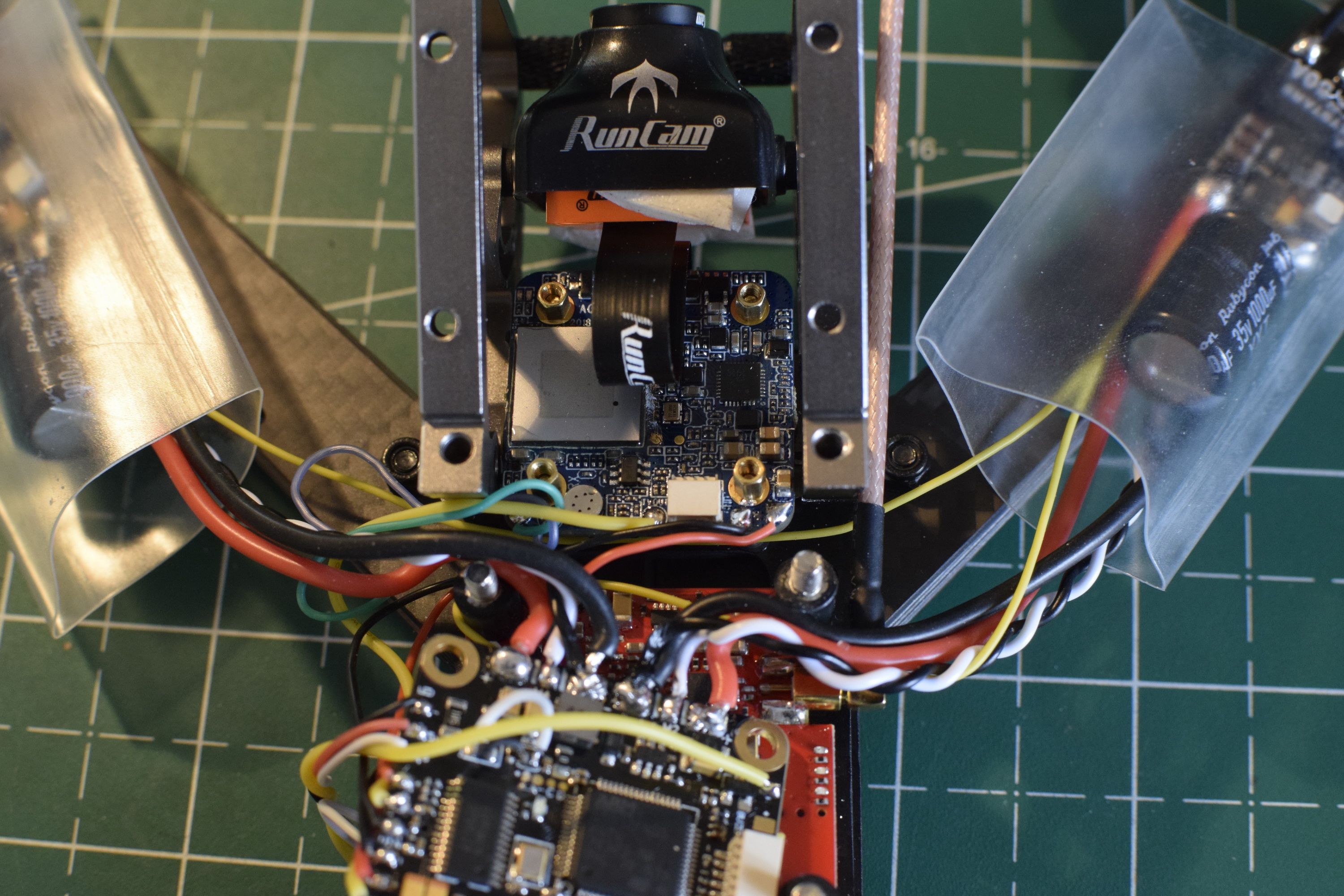

Please note that the split mini 2 comes with a camera adapter that I did not use (I used this adapter for another build)
This is why I had to reuse the case of burnt swift 2 and you can see the messy double sided foam.
I ordered a micro to full size adapter and should receive it soon.
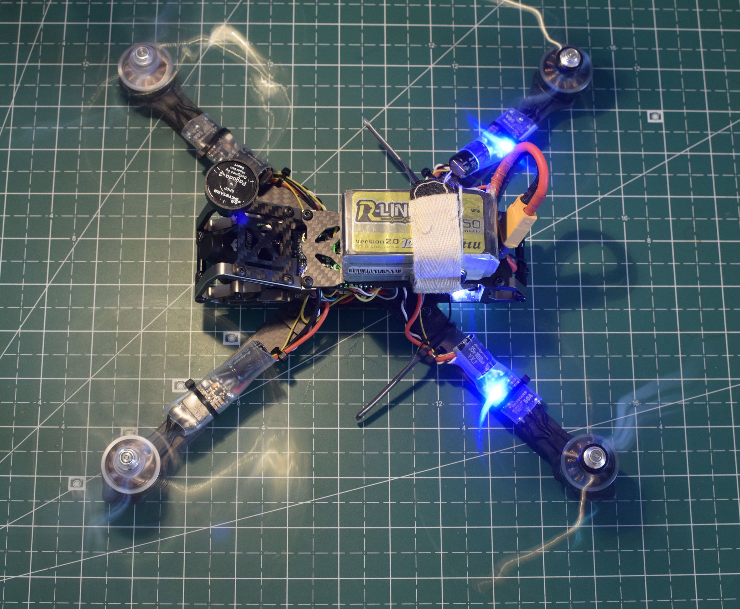
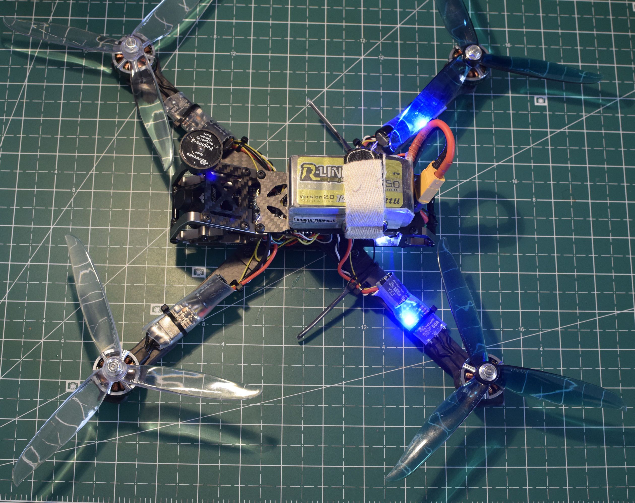
Check the galery for more pictures
It's time for maiden flight. I hope this guide will be useful to someone, please don't hesitate to ask for help in the comments.
Photos


Part List
Frame |
CA$266.52 Skystars G730L 300mm F4 OSD 50A BL_32 7 Inch FPV Racing Drone w/ Runcam Swift 2 WDR Camera PNP RC Toys & Hobbies fr
Banggood.com
|
$266.52 |
FPV Camera |
RunCam Split Mini 2 FOV 130 Degree 1080P/60fps HD Recording & WDR FPV Camera NTSC/PAL Switchable
(89 builds)
Banggood.com
|
$69.99 |
Misc Parts |
Dual BN-220 GPS GLONASS Antenna Module TTL Level RC Drone Airplane
(12 builds)
Banggood.com
|
$11.99 |

Guides & Reviews
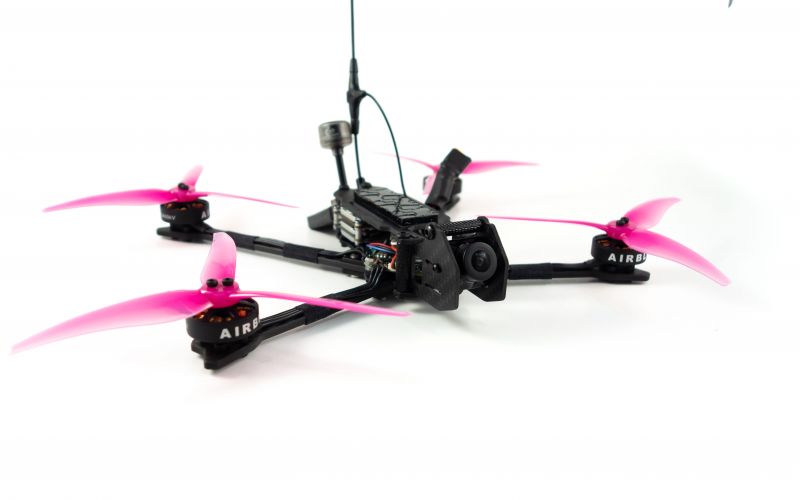
AirbladeUAV has done it again and this time they've brought long range to the 5" class! Based on the popular Transformer Mini, the new Transformer 5" Ultralight adopts a lot of the same design philosophies with larger props and more payload capacity. It can fly upwards of 20 minutes on a 4 cell Li-Ion battery pack and in ideal conditions it's got a range of over 4 to 5 miles. In this guide I'll walk..
Read more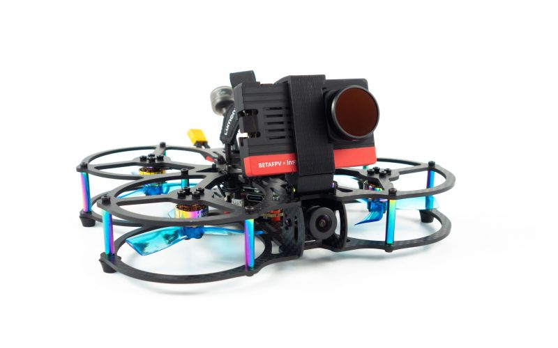
With the release of the DJI FPV Drone cinematic FPV has become a lot more accessible, but you certainly don't want to crash a $750 drone! The QAV-CINE Freybott is a compact, lightweight cinematic FPV drone that can take a hit and keep going. It's a lot safer to fly indoors and around people. With a naked GoPro or the SMO 4k you can capture some great stabilized footage. In this guide I'll show you..
Read more


Can you please post the link for the micro to full size camera adaptor. I recently bought the split 4 (14mm, not 19 like the split 3).
I mounted the PCB on the top where the GPS/Cam would go and moved some things around. GPS got strapped down to top plate in front of gopro.
Yes the GoPro Fusion is ridiculously heavy lol.
here you go... this is what I use now and it is much better then what you see in the pictures https://www.banggood.com/2-PCS-Micro-Camera-Mount-Bracket-for-RunCam-Micro-Sparrow-2-ProMicro-Eagle-p-1318078.html?rmmds=myorder
thank you sir. just picked one up at RDQ, worked great! have you done much with this quad since the build?
I noticed some potential ESC desyncs. Have you experimented much with BLHeli or tuning in general?