American Muscle Quad V2 (Full Build Log)
 By PeregrineFPV on Oct 09, 2017
There were three main motives to this build: 1. Go Fast (3-6s) 2. Get smooth HD video 3. Be easily repairable after inevitable crashes. This build is full featured with silicone conformal water proofing, 3-6s capability, up to 800mw of video transmitting power, MicroSD BlackBox logging, DSHOT ESC’s, OSD, current sensor, and SmartAudio. Telemetry can also be wired into this build, but I chose not to.
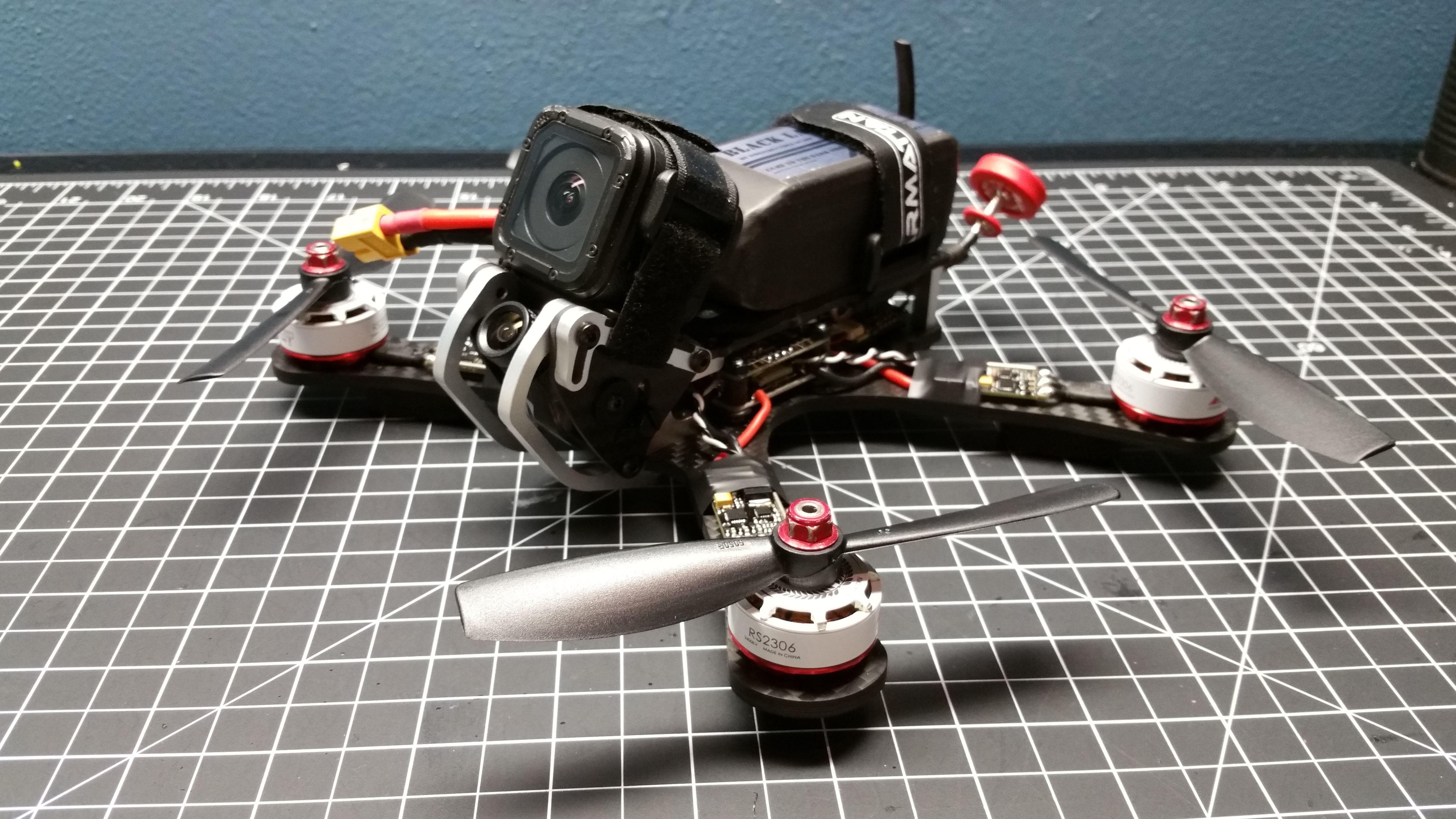
All Up Weight: 646g = (Quad with props and straps = 395g) + (Battery = 178g) + (GoPro = 73g)
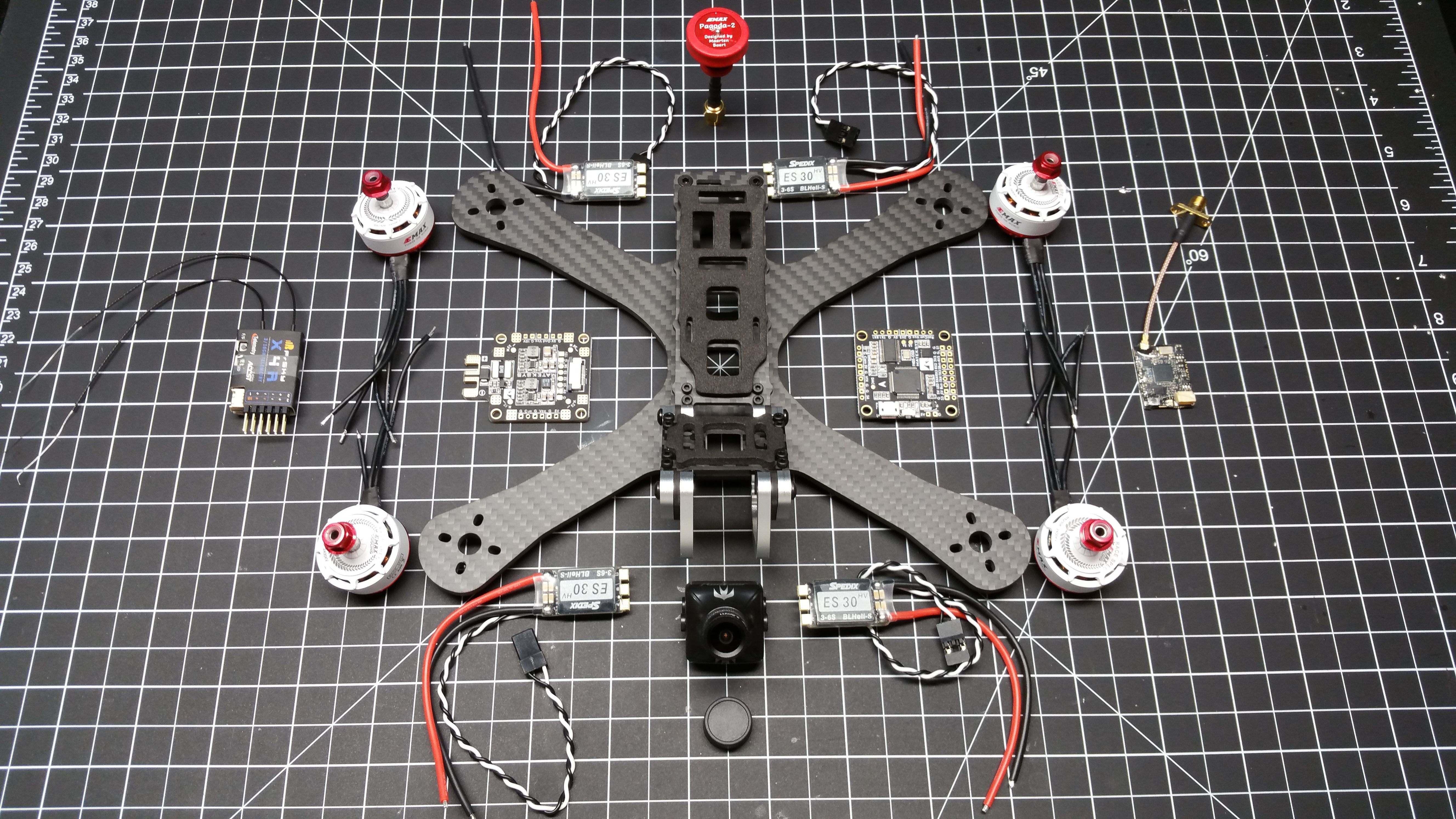
The Parts

A little knolling here for a good time. This photo only shows the hardware. There are many other things that helped make this build possible. Some of the other items used in this build:
Materials: Zip ties, blue loctite, various gauges of wire, XT60 connector, heat shrink, VHB tape, electrical tape.
Tools: Hex Drivers, soldering iron & solder, multi-meter, Xacto knife, hemostats/forceps.
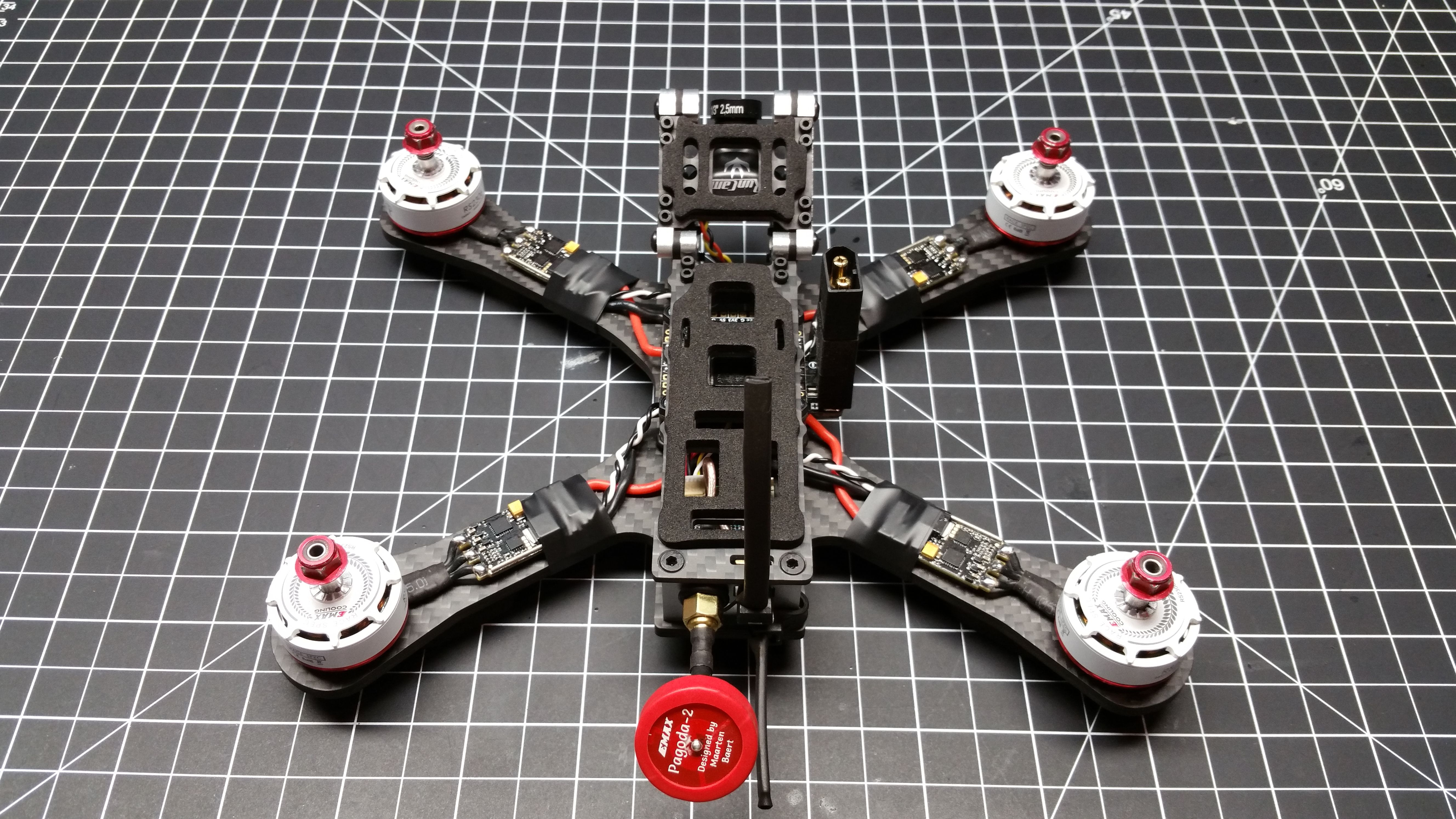
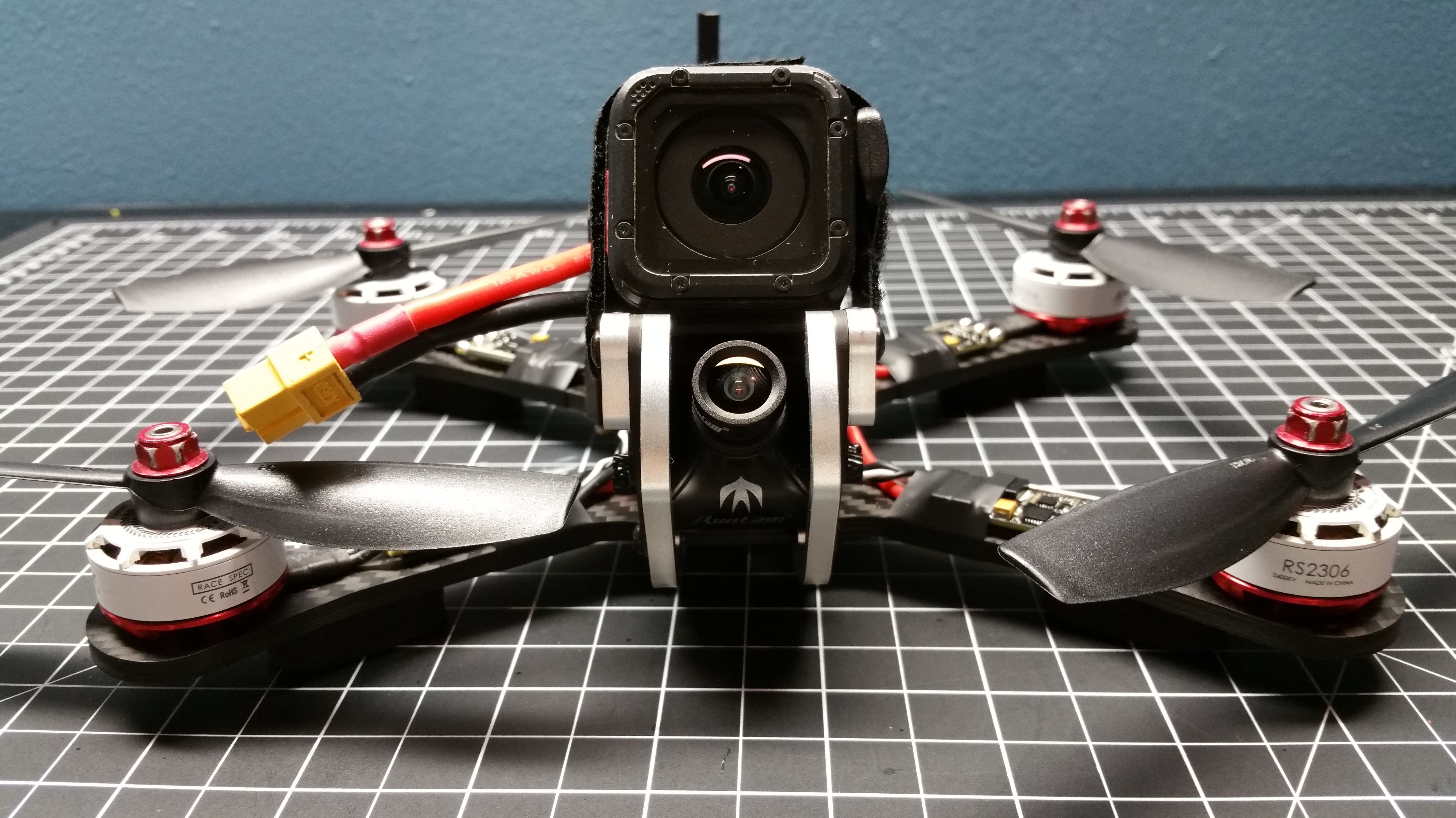
The Frame

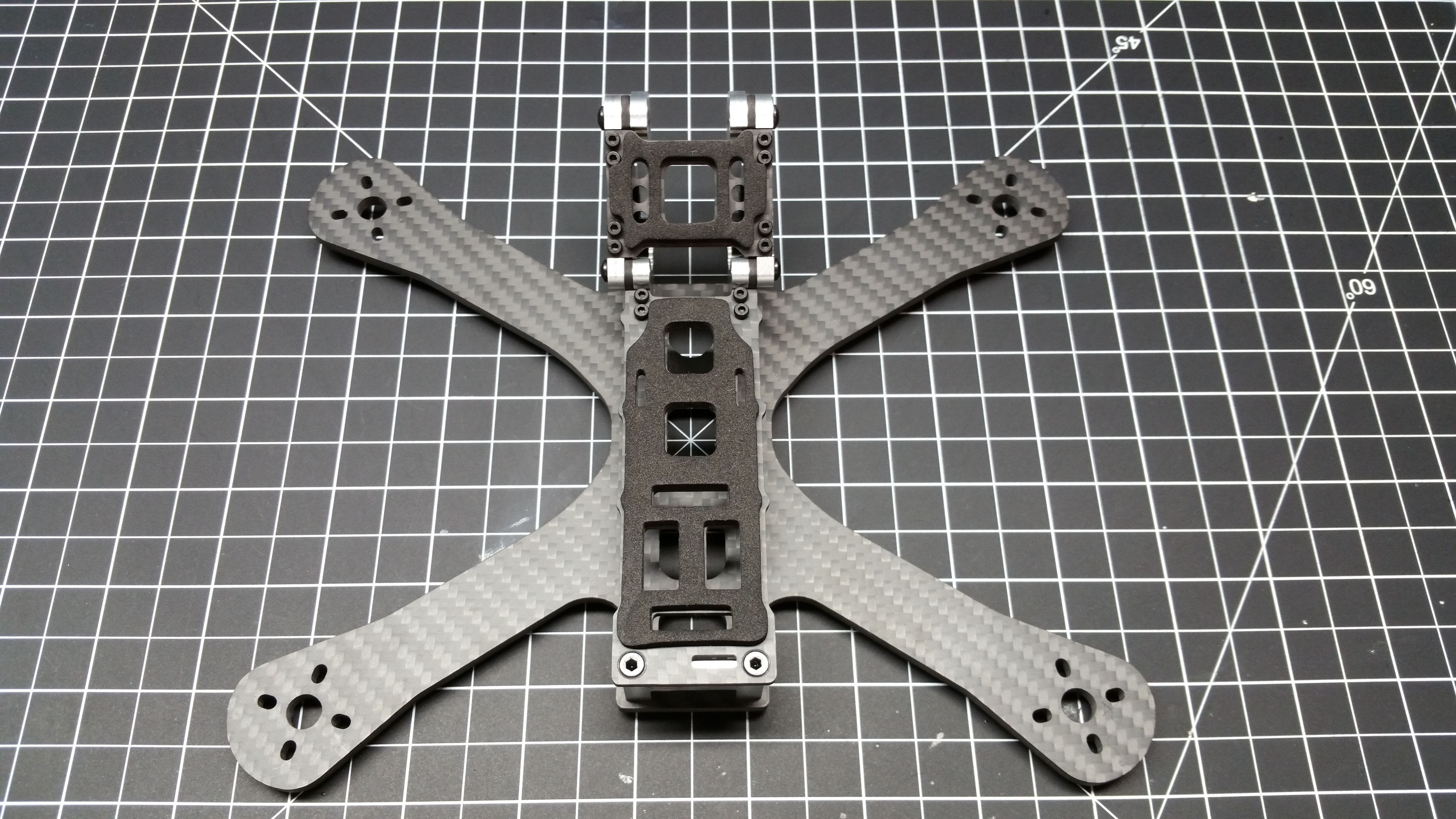
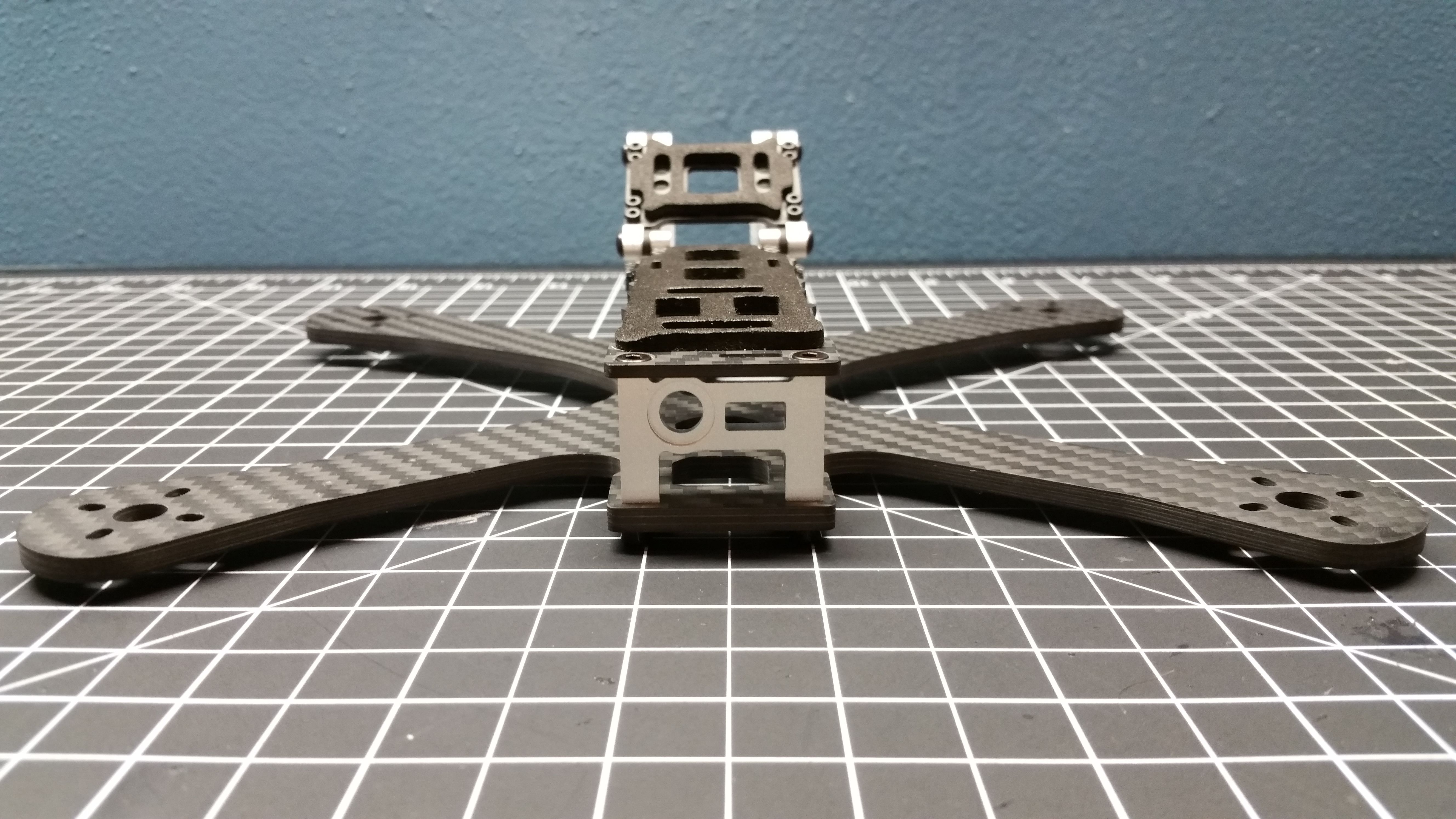
I chose the 5" Chameleon frame because of the robust design and general solid construction. I like the idea of a protected and detachable camera cage that I can swap out after a hard crash and keep on flying. Armattan is a very reputable company and the only one that I am aware of that offers a LIFETIME WARRANTY on their frames. So, this was a no brainer.
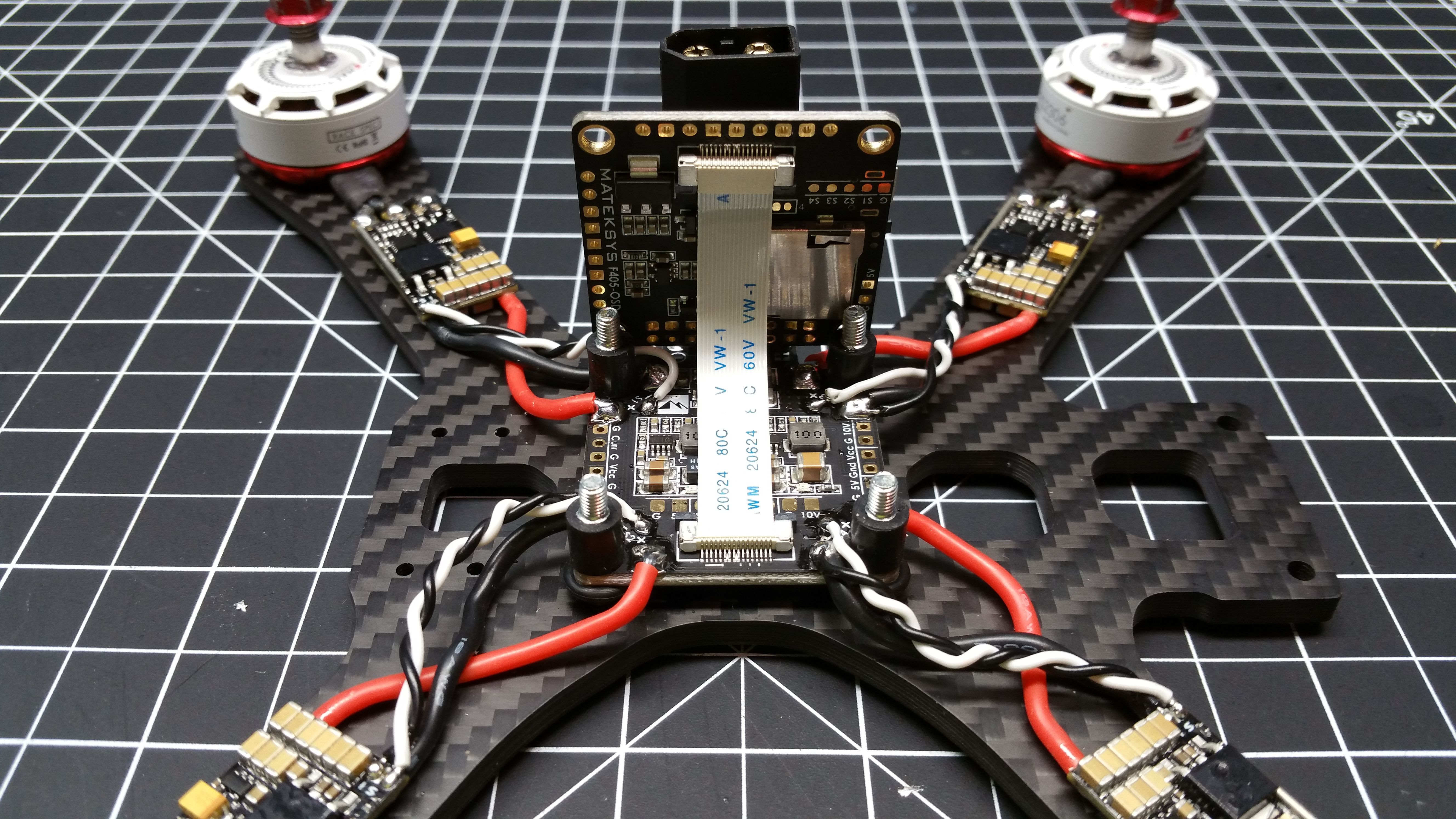
Power Distribution

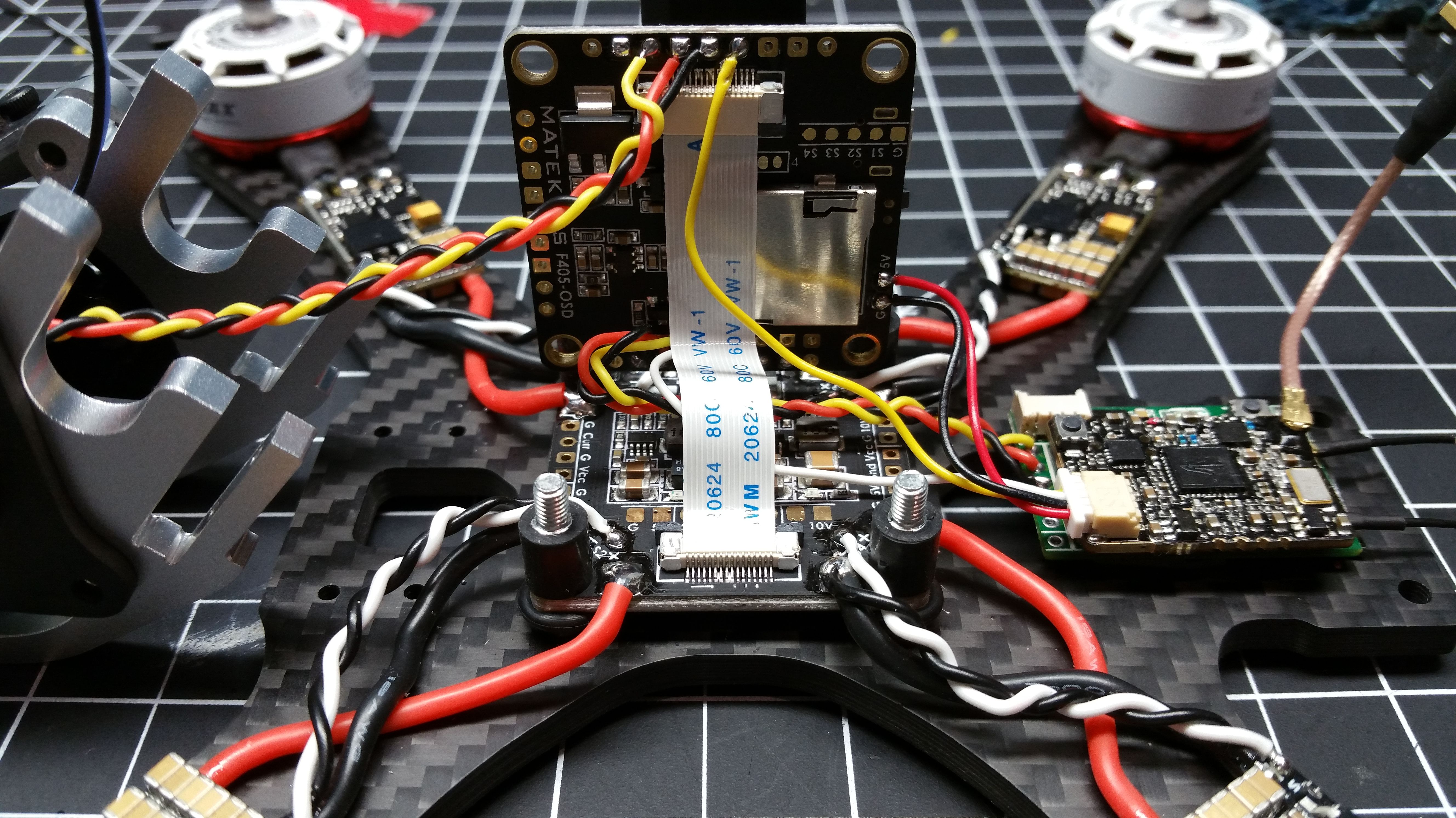
Here we have the Matek FCHUB PDB. This board pairs with the Matek f405 Flight controller. All the critical connections from the PDB to the flight controller are made through a ribbon cable.
The XT60 plug is connected to the PDB through 12 AWG wire. The wire is fed through 2 of the “connector savers” that Armattan sells for their PDB. It’s not totally necessary to use these, but I like them. To use these with this PDB, I had to cut a chuck out the bottom one to make room for the electrical component on the PCB right next to the power leads. Kind of a pain, but it helps clean up the build.
Coat the bottom of the PDB with conformal coating before mounting the board.
This is mounted via a nylon bolt, then a nut, followed by an o-ring, fthen finally the PDB.
ESCs and Motors

ESC: Spedix 30 Amps were chosen due to their 3-6s capabilities. They offer 40 amps of burst current for a total of 160 amps. The PDB can handle 184 amps of current, so these fall within the limits of that. These ESC’s can run DSHOT 600. Betaflight 3.2 has introduced some new features that require DSHOT such as “Anti-Turtle” mode and using the motors as beepers.
Once the ESC’s are connected to the motors, baste them with some conformal coating. Then VHB tape them to the frame.
Solder the PDB

This part is pretty straight forward. Positive to positive and negative to negative. Solder the signal wire to the signal pad and solder the negative signal wire to the negative esc pad with the negative esc wire.
Once its wired up paint it with some conformal coating.
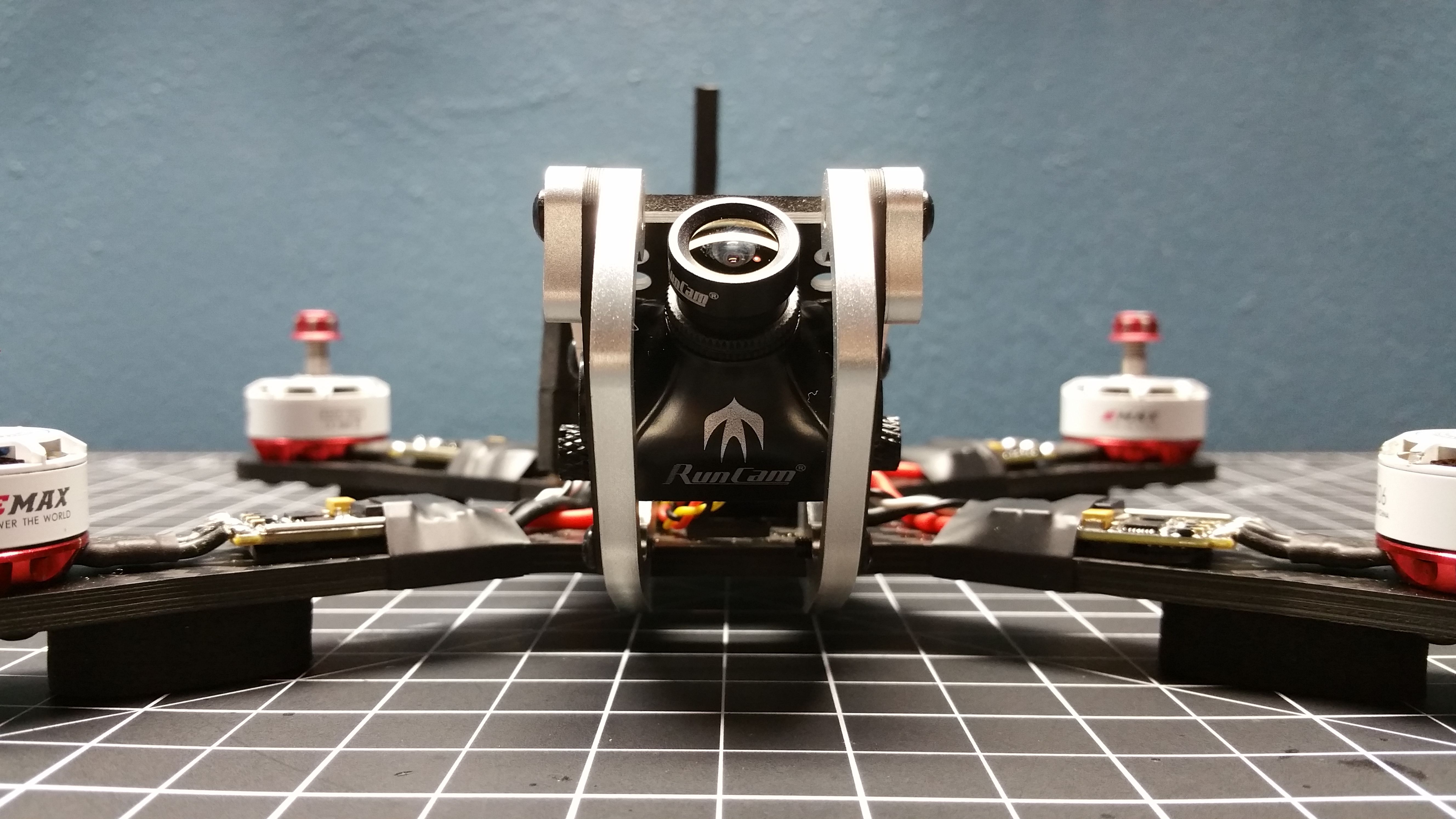
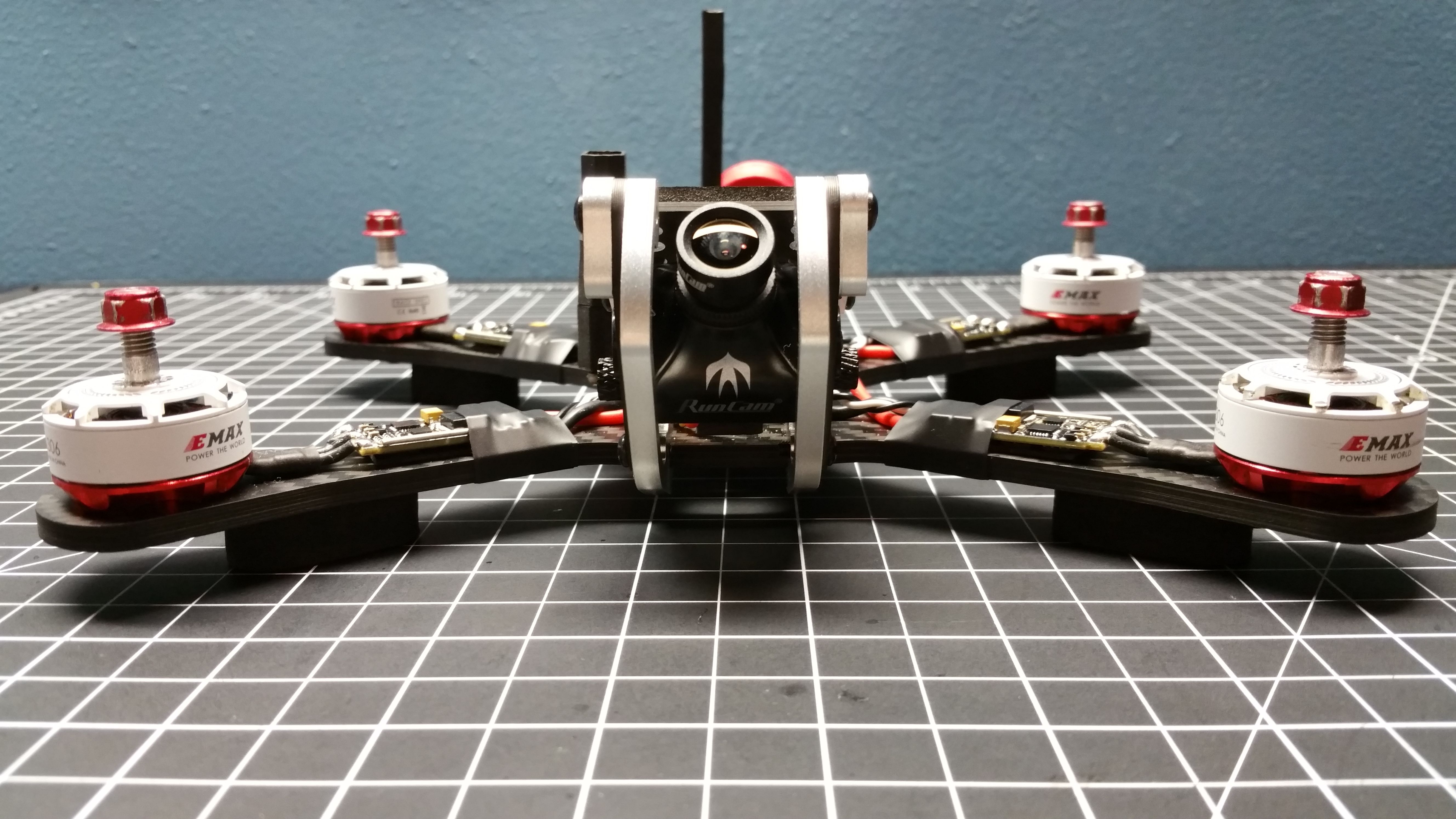
Camera Pod

The camera case that the Swift 2 comes with needs to be swapped out for the flat back one included. There are 2 phillips screws that hold the back case on that need to be removed to swap the back plate out.
I removed the audio (white) and VBAT (blue) wires from the connector because I won’t be using the audio from the onboard mic, or the OSD that the RunCam has. You can either cut them or completely remove them from them from the connector.
You can also see that I left the OSD configurator jumper plugged in. This is not necessary.
And most importantly, braid the wires for style points.
Radio Receiver and Video Transmitter

Receiver: Any small-ish receiver can really take the place of the X4R, so long as it hears the same protocol your radio speaks. Since I was not using telemetry on this build, an XM+ receiver would have been a better option. I already had an X4R receiver with the pins still attached, so that’s what I used. I de-pinned the RX to reduce the size and make it so I can directly solder to it. As seen in the picture: yellow is SBUS, red is 5v power, and black is ground. More technical specs around general wiring and wiring up telemetry can be found on the Matek F405 information website. I had also shortened the antennas significantly since they come very long.
Transmitter: I chose the V2 version of the TBS Unify Pro series of VTX. This particular model does NOT take full battery voltage like the other varieties. Instead, the V2 takes 5v of power. I chose this because of that very reason. I have heard a lot of people having issues with the full voltage versions producing video black outs and black lines across the video feed. I suppose this could be circumvented by feeding the full voltage version a regulated power source, but I caught the V2 on sale.
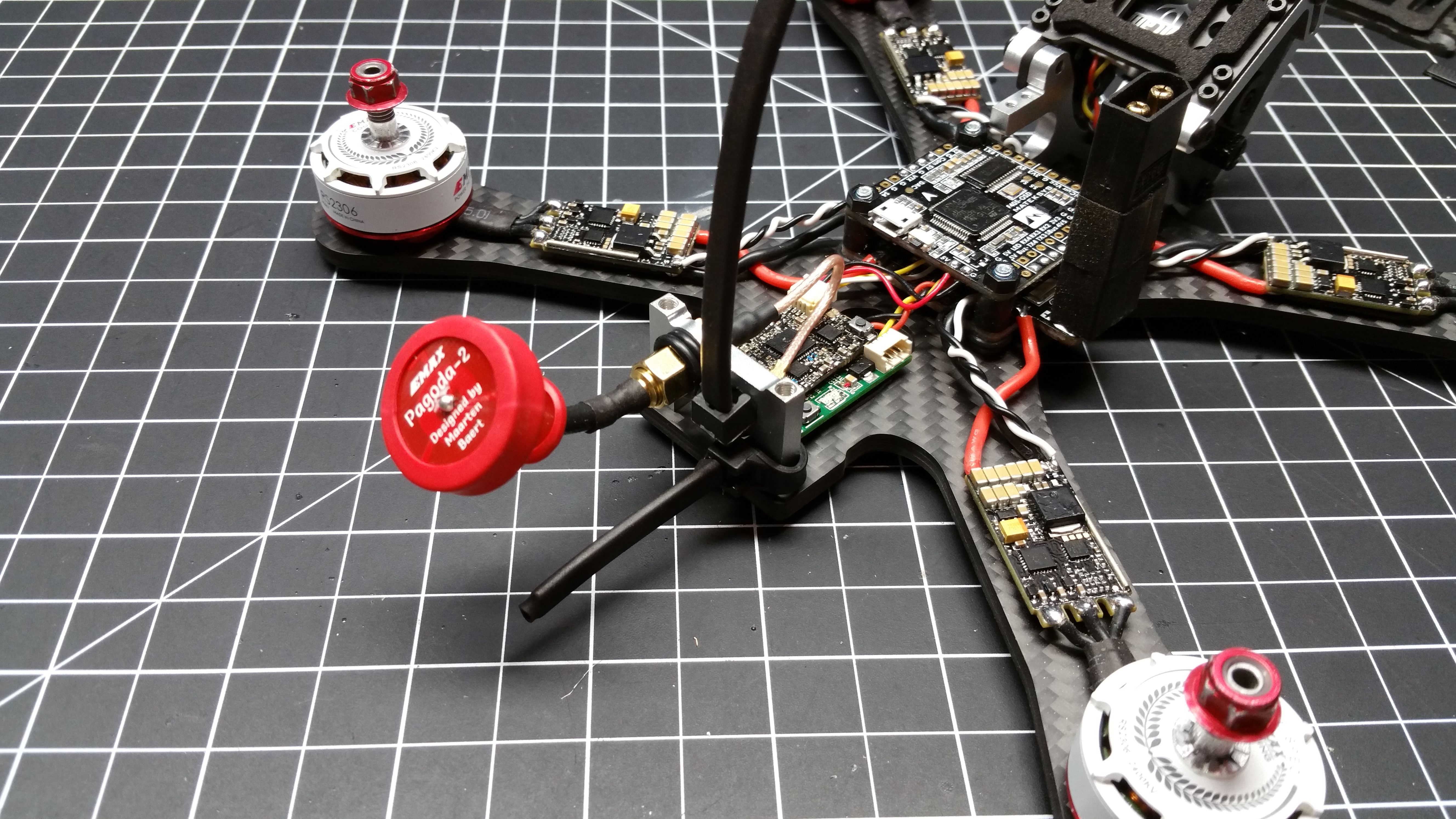
I then used VHB two-sided tape to mount the boards to the frame. The RX is taped to the frame, and the VTX is taped onto the RX.
Once all the wires are connected to the VTX/RX season them in conformal coating before mounting to the frame.
Flight Controller

Matek does a wonderful job providing clear and easy to understand directions for wiring their FC so I won’t go too in-depth.
I used the included vibration isolating standoffs that the flight controller comes with to mount this in the stack.
One thing to note here. Make sure you power the VTX with ONLY 5V. The 5v pads I chose to power the VTX interfere with the BlackBox SD card slot. This is sort of bitter sweet. Make sure you insert your card before soldering those wires in place. Either that or solder the wires top-side to keep them out of the way. Doing it this way helps prevent the SD card from being ejected however.
Once all the wiring is done, slather it in conformal coating.
Information and wiring diagrams regarding this FC can be found here: http://www.mateksys.com/?portfolio=f405-osd
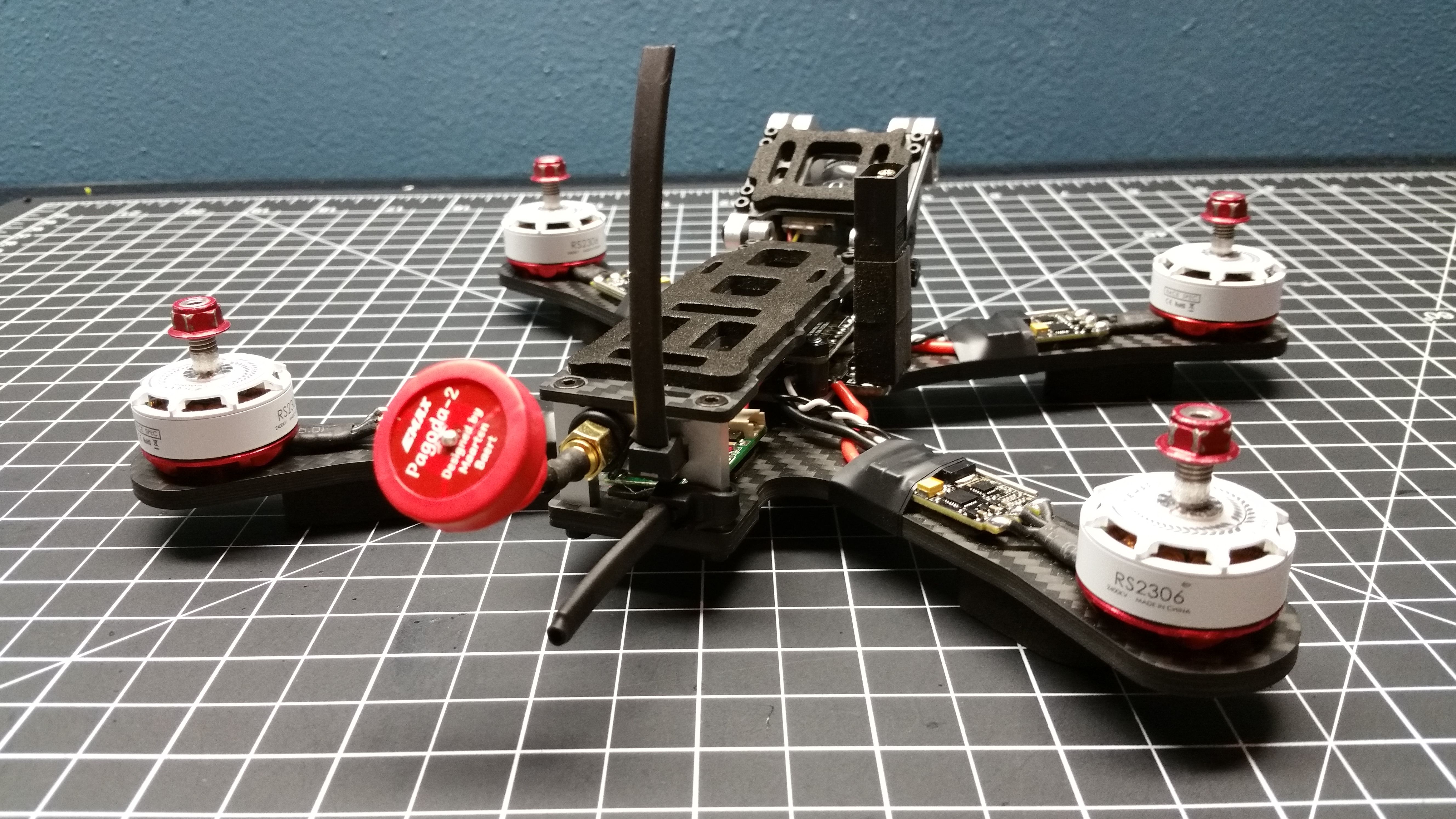
Modify the VTX SMA connector

One step I forgot, was that the Unify Pro pigtail does not fit the Chameleon frame unless modified. I used a bench grinder to remove the two wings from the SMA connector as seen in the picture.
Mount the Antennas

I used zip ties and heat shrink to mount the RX antennas 90° to each other. This configuration should give you the best RF diversity. An alternate antenna mounting solution can be seen in my original “American Muscle Quad” post. The original American Muscle Quad can be found here https://rotorbuilds.com/build/3933
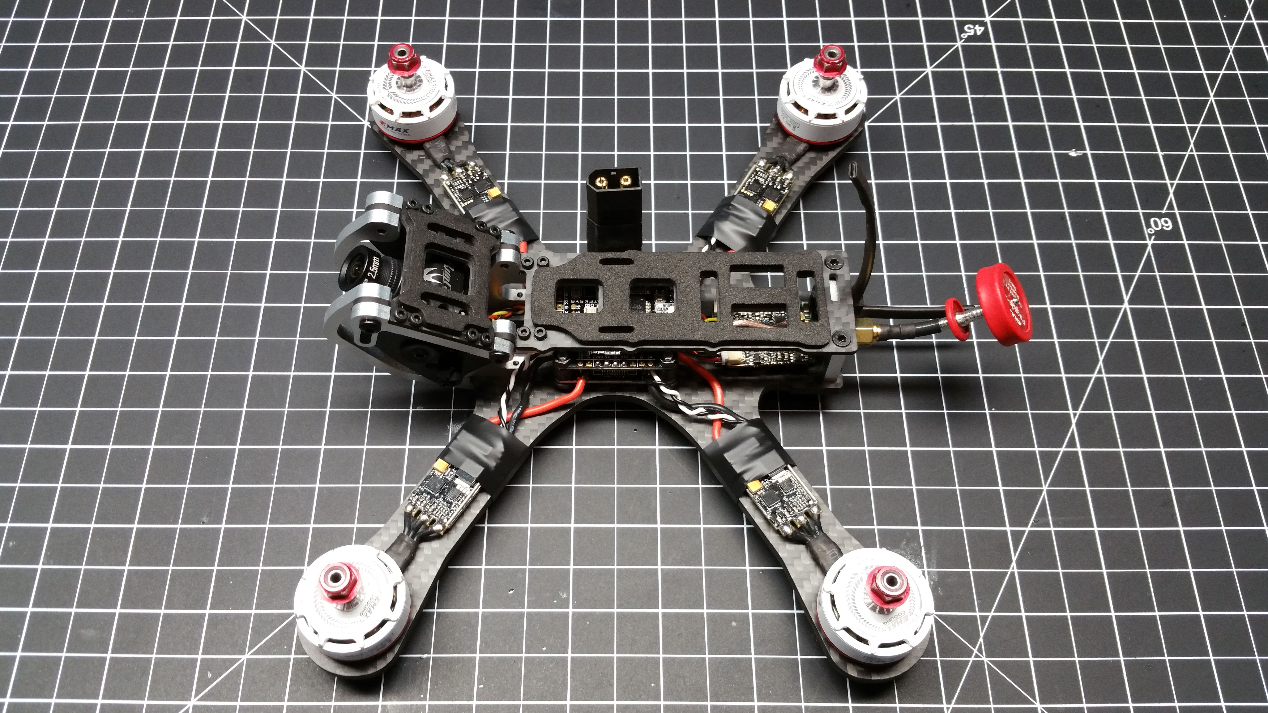
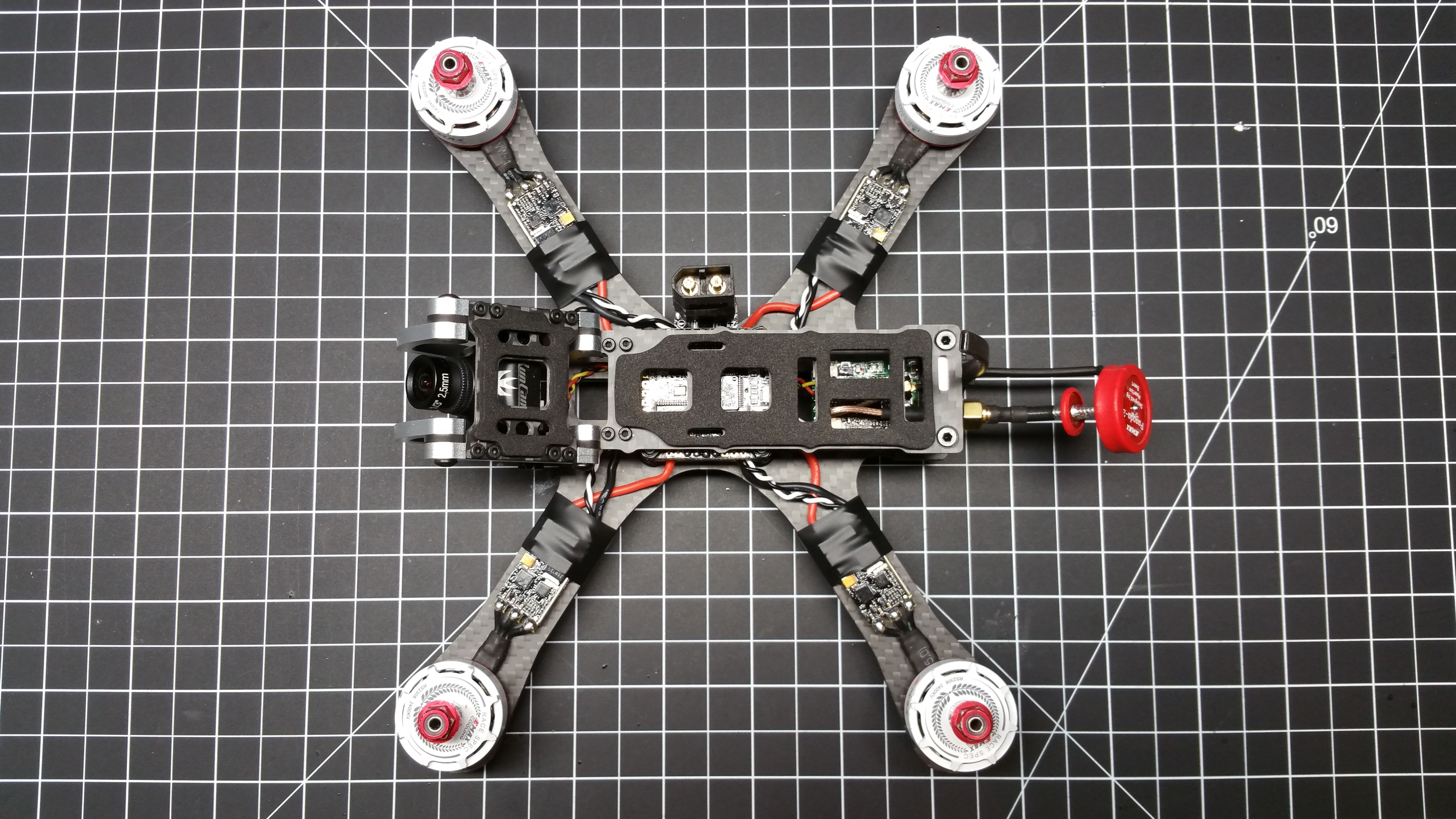
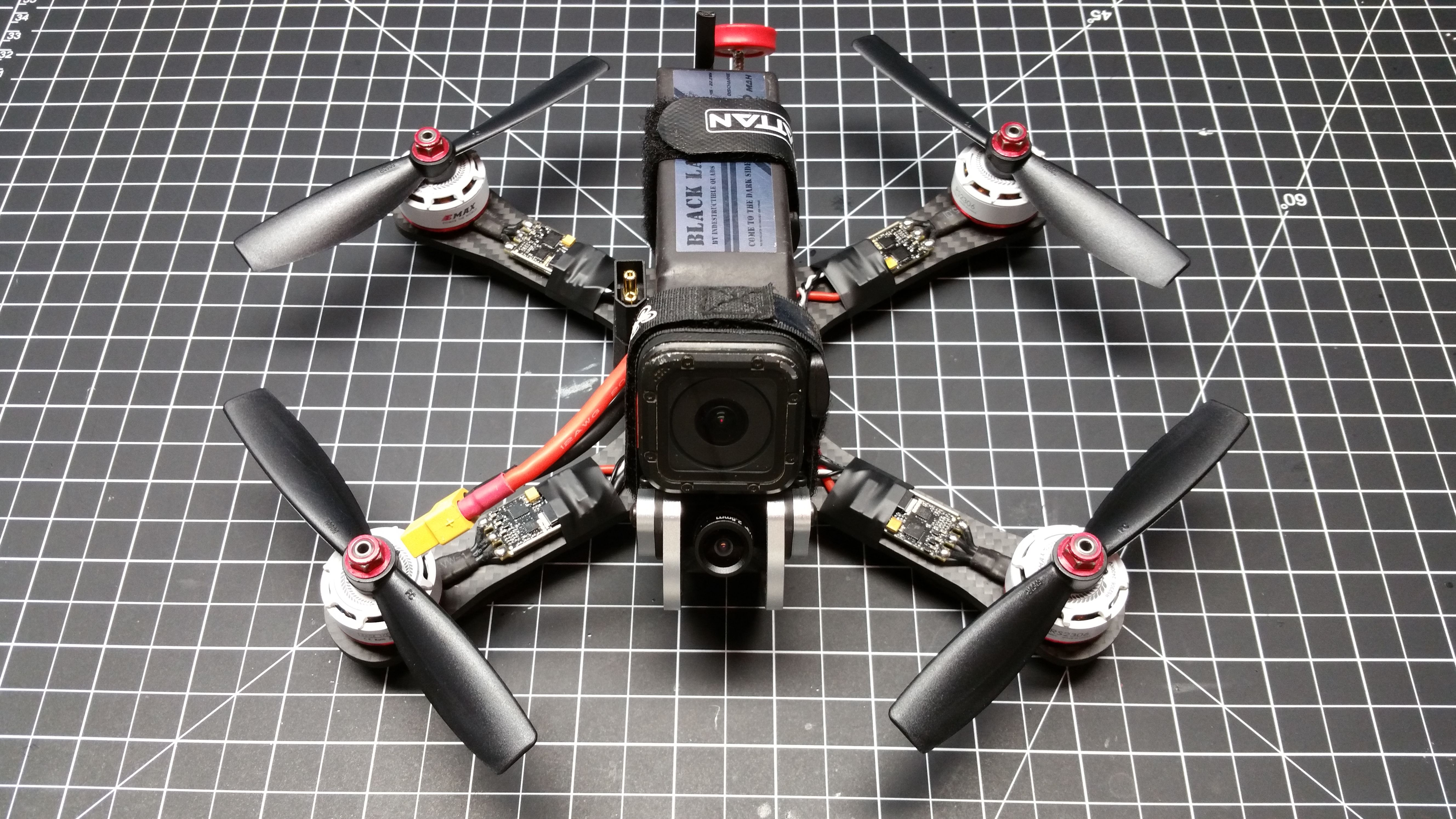
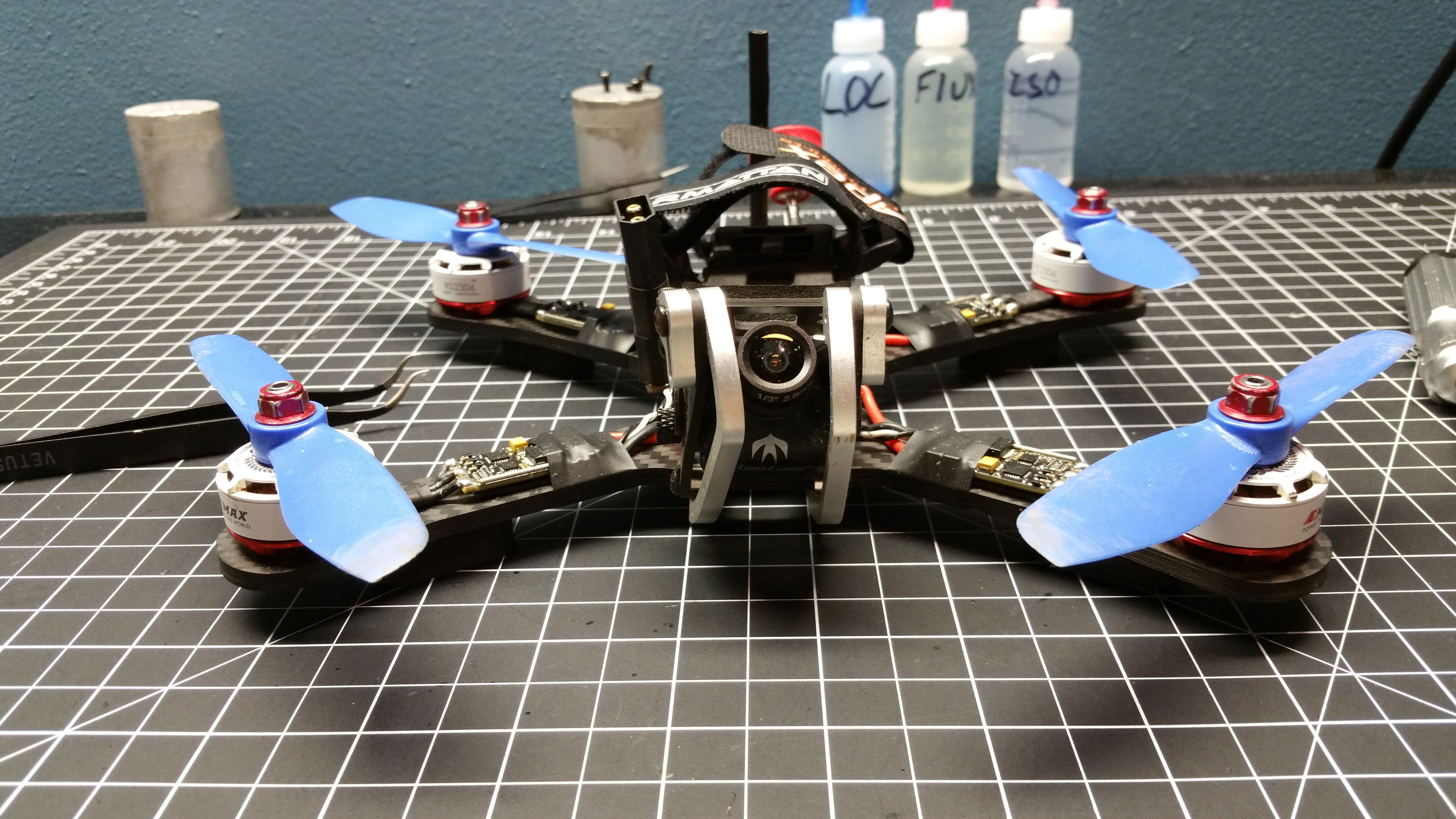
Finishing Up

Here it is in all its glory. I ran through and made sure all frame hardware had Loctite on and was tightened properly.
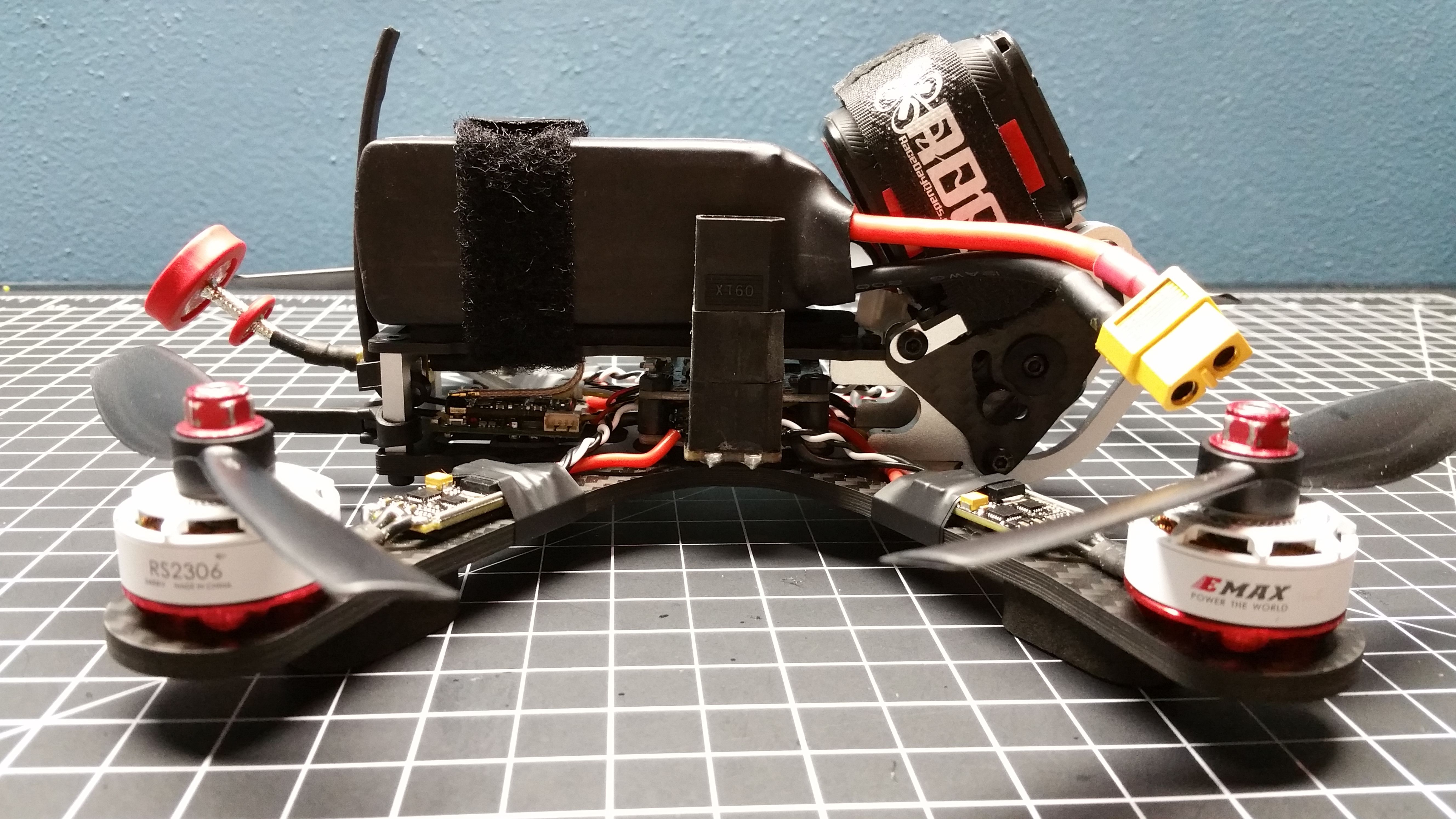
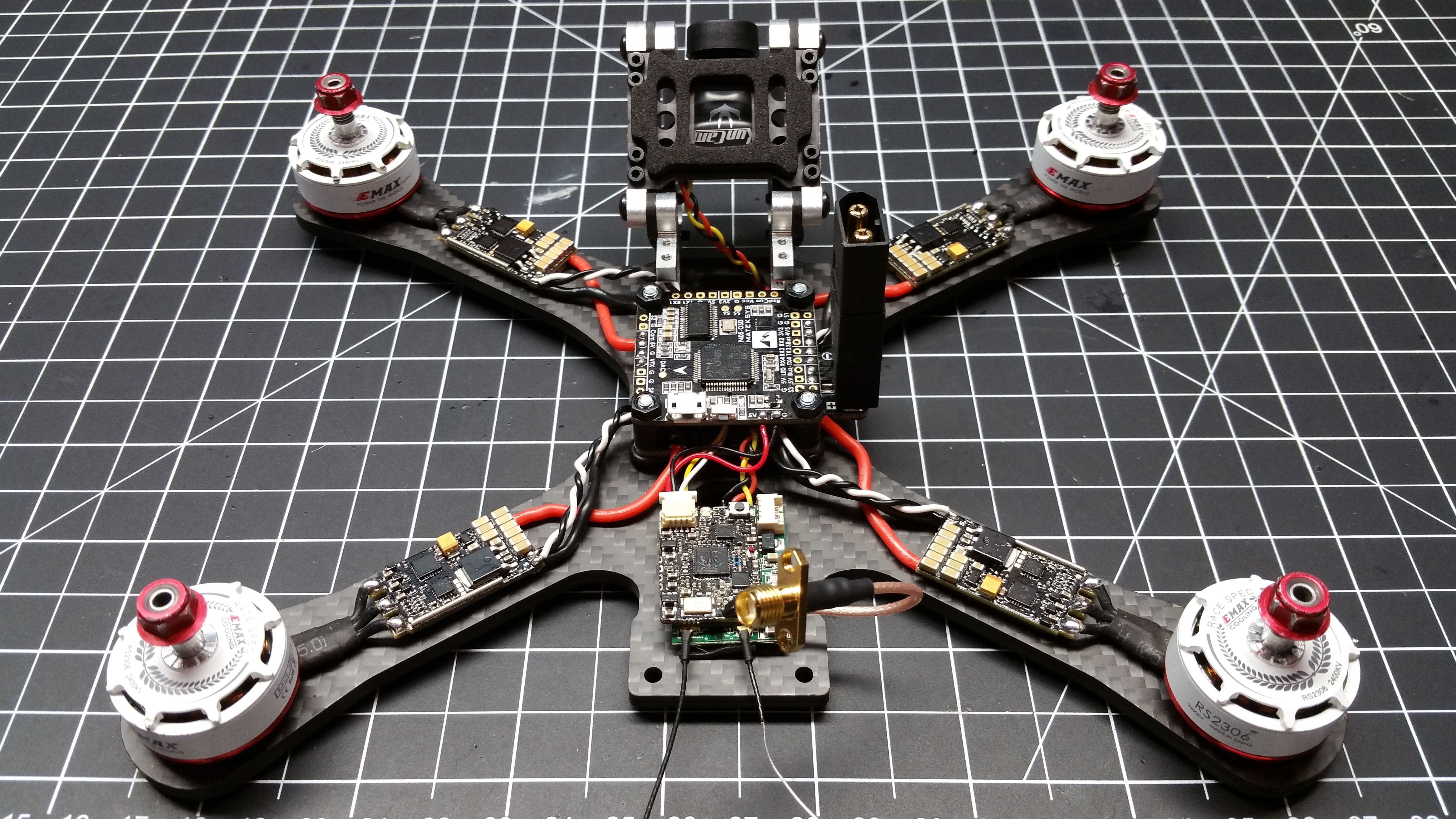
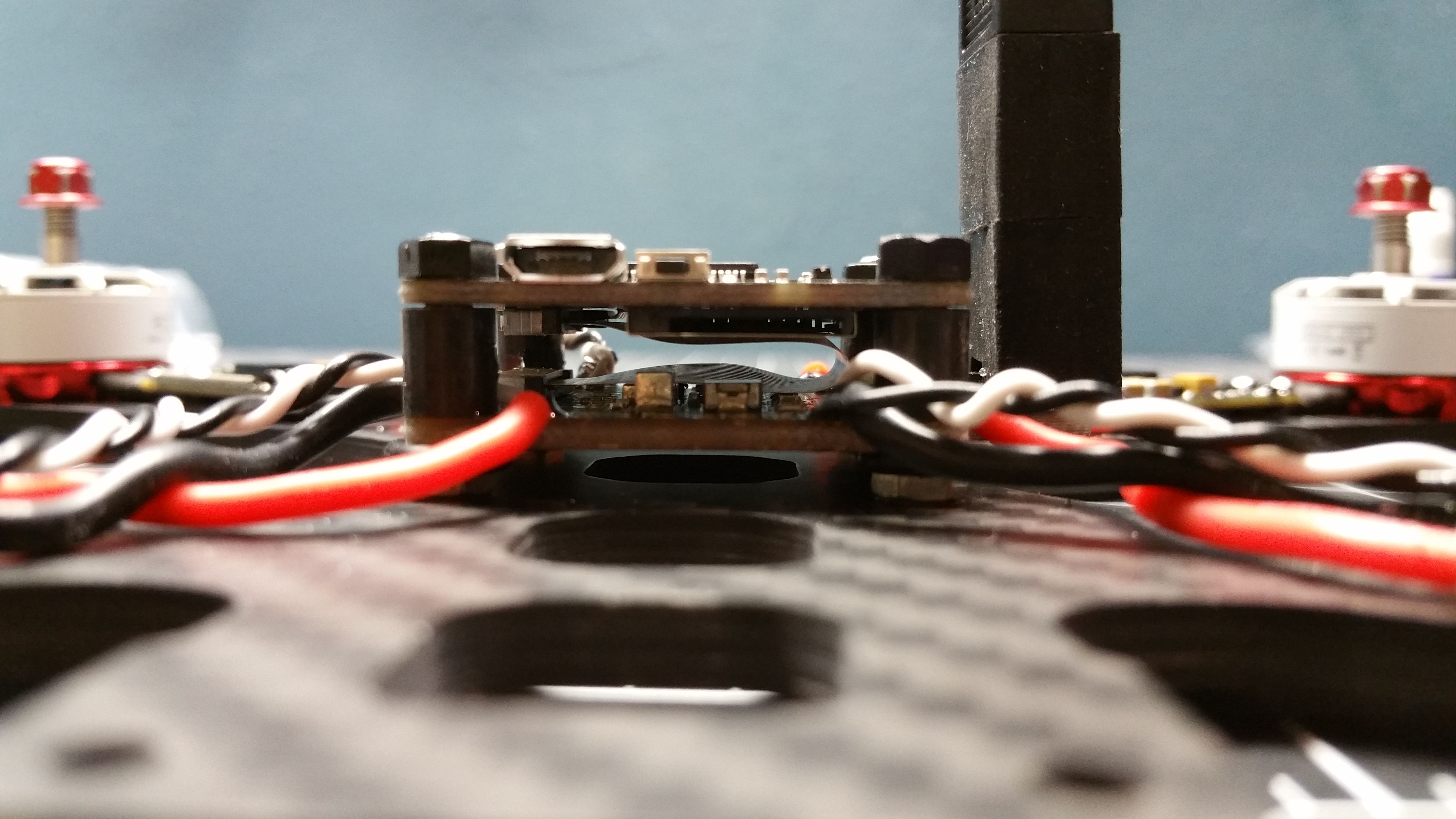
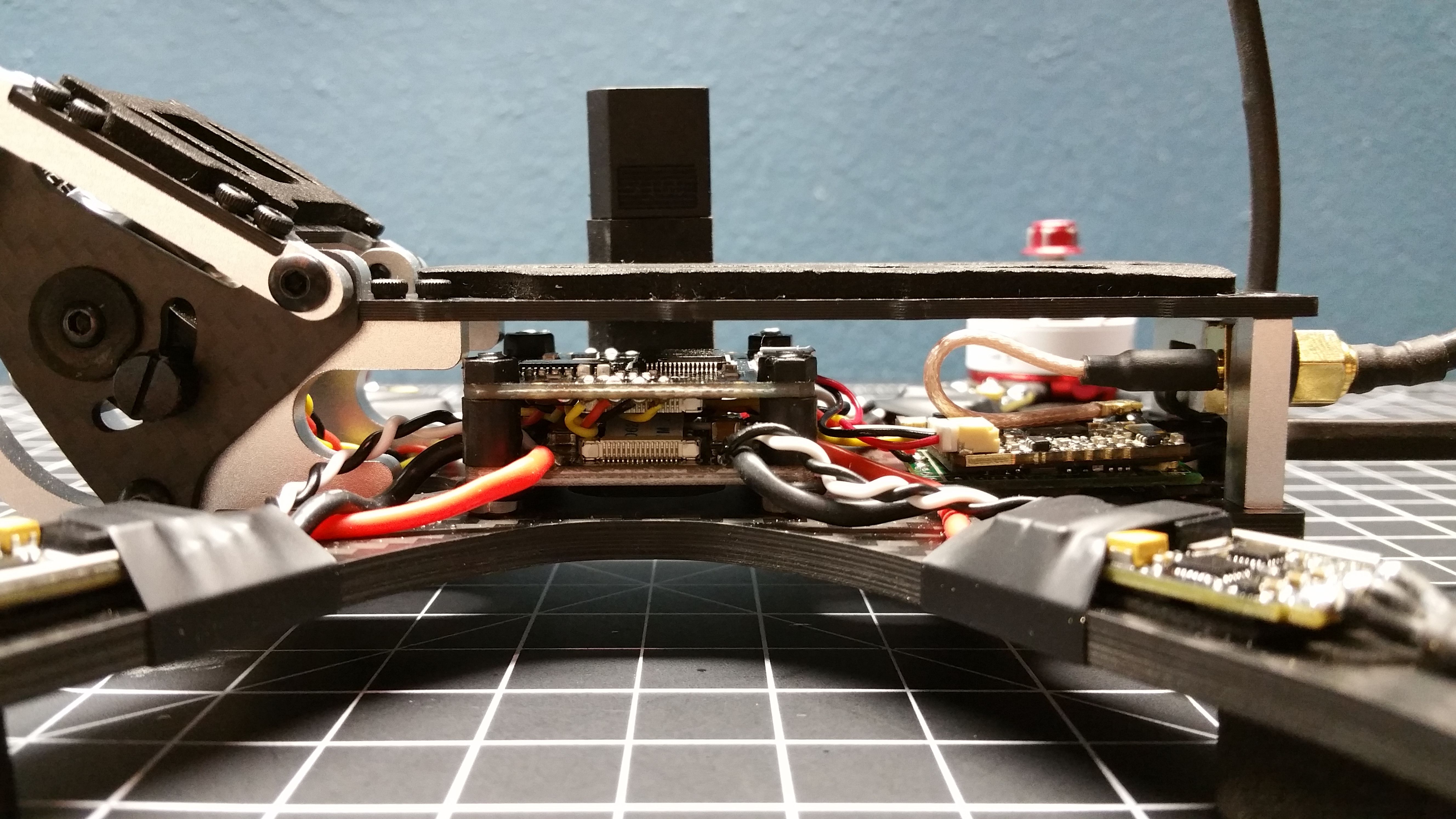
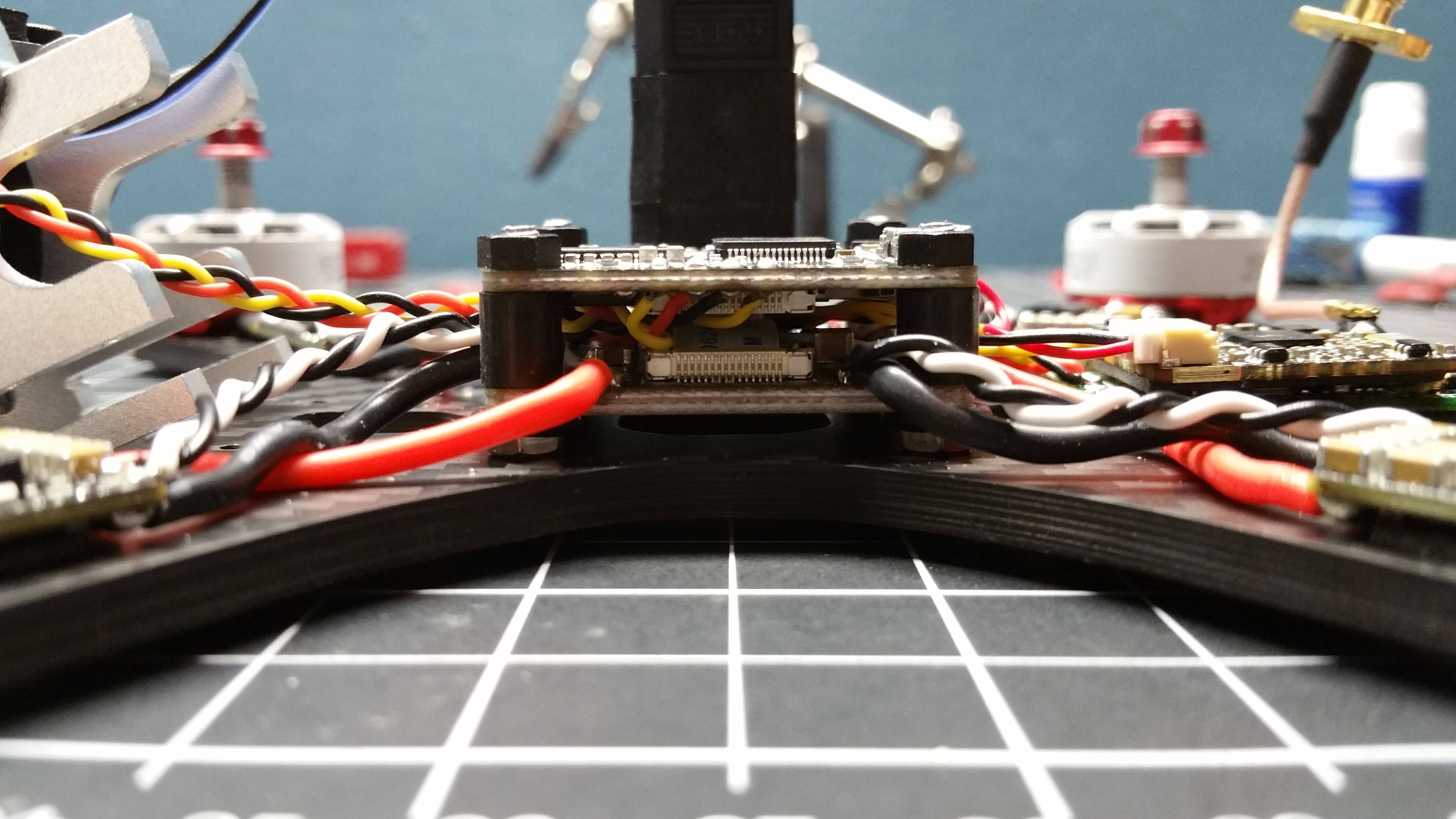
The Stack

My stack can beat up your stack…
Betaflight Configuration

The unfortunate part about this build is the minor difficulty plugging into the usb port on the quad. If you have a right angle usb plug, then it is no problem. Since the flight controller is mounted with the “forward” direction facing another way, the motors must be remapped and the orientation in BetaFlight must be changed.
To remap the motor inputs, go to the CLI in BetaFlight and enter the following code:
resource MOTOR 1 NONE
resource MOTOR 2 NONE
resource MOTOR 3 NONE
resource MOTOR 4 NONE
resource MOTOR 1 C08
resource MOTOR 2 C06
resource MOTOR 3 C09
resource MOTOR 4 C07
save
The board orientation can be changed in the configuration tab by changing the “GYRO alignment”, “ACCEL alignment” and “MAG alignment” to CW 90°
The last build specific configurations are calibrating the current meter. Set both “Voltage Meter Source” and “Current Meter Source” to “Onboard ADC”. My settings for this are “Battery Voltage Scale” = 110 & “Battery Amperage Scale” = 179
This build had no problems removing ALL notch filters. I am running the “Dynamic Filter” currently.
There are countless tutorials and videos going in-depth about BetaFlight configuring, so I will spare you and myself.
Welcome to the Hobby

On my 3rd flight, I smoked a tree head on at nearly full speed. This was the result.
Stay high.
Photos


Part List
Frame |
Chameleon
(164 builds)
Armattanquads.com
|
$90.00 |
Flight Controller |
Matek F405-OSD BetaFlight STM32F405 Flight Controller Built-in OSD Inverter for SBUS Input
(102 builds)
Banggood.com
|
$27.99 |
ESCs |
4 x Spedix ES30 HV 3-6S 30A ESCDefault Title
(154 builds)
Racedayquads.com
|
$47.80 |
Motors |
4 x EMAX RS2306 White Edition 2400kv FPV Racing Motor
(87 builds)
Racedayquads.com
|
$79.96 |
FPV Camera |
RunCam Swift 2
(202 builds)
Shop.runcam.com
|
$44.99 |
FPV Transmitter |
TBS Unify Pro 5G8 V3 (SMA)
(154 builds)
Team-blacksheep.com
|
$40.95 |
Antenna |
EMAX Pagoda Antenna RHCP Set of 2 - 50mm and 80mm
(62 builds)
Racedayquads.com
|
$14.99 |
Receiver |
FrSky X4R-SB - 3/16 Channel Receiver with SBUS and CPPM without pins
(128 builds)
Getfpv.com
|
$22.49 |
Power Distribution |
Matek FCHUB-6S Hub Power Distribution Board 5V & 10V BEC Built-in 184A Current Sensor for RC Drone
(96 builds)
Banggood.com
|
$9.99 |
HD Camera |
GoPro Hero5 Session, 1080p
(302 builds)
Amazon.com
|
$230.41 |

There is any reason why these esc so expose?
No real reason. Mostly because I mounted them MOSFETS down and wanted to make sure enough air could get to them to cool them off. Whether that actually help or not, I'm not sure. I also like to not have electrical tape in the way when I want to swap motors or mount the landing pads underneath. All the components have silicone conformal coating applied to them, so I'm not too worried about them shorting out on anything. I put a couple wraps of tape around where a prop strike might happen and called it good enough.
Guides & Reviews
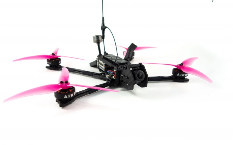
AirbladeUAV has done it again and this time they've brought long range to the 5" class! Based on the popular Transformer Mini, the new Transformer 5" Ultralight adopts a lot of the same design philosophies with larger props and more payload capacity. It can fly upwards of 20 minutes on a 4 cell Li-Ion battery pack and in ideal conditions it's got a range of over 4 to 5 miles. In this guide I'll walk..
Read more
With the release of the DJI FPV Drone cinematic FPV has become a lot more accessible, but you certainly don't want to crash a $750 drone! The QAV-CINE Freybott is a compact, lightweight cinematic FPV drone that can take a hit and keep going. It's a lot safer to fly indoors and around people. With a naked GoPro or the SMO 4k you can capture some great stabilized footage. In this guide I'll show you..
Read more


Very Very nice !! :)