
The idea was to build a capable 2" quad to raise less safety concerns than a typical 5" would to be able to fly in local parks during the day.
It also should have had a good FPV camera, a decent range receiver and a VTX capable of more than 25mW because flying behind trees is fun.
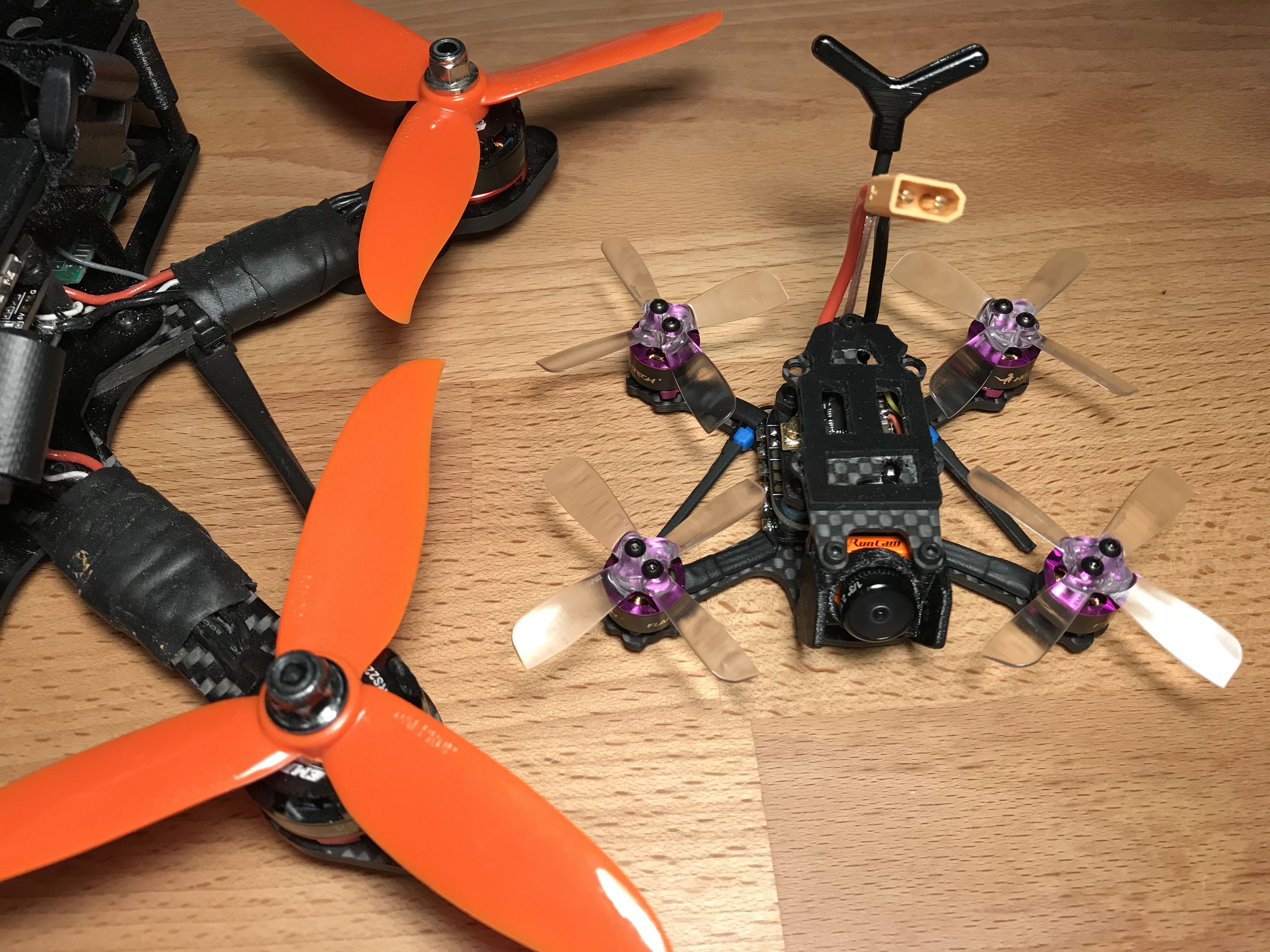
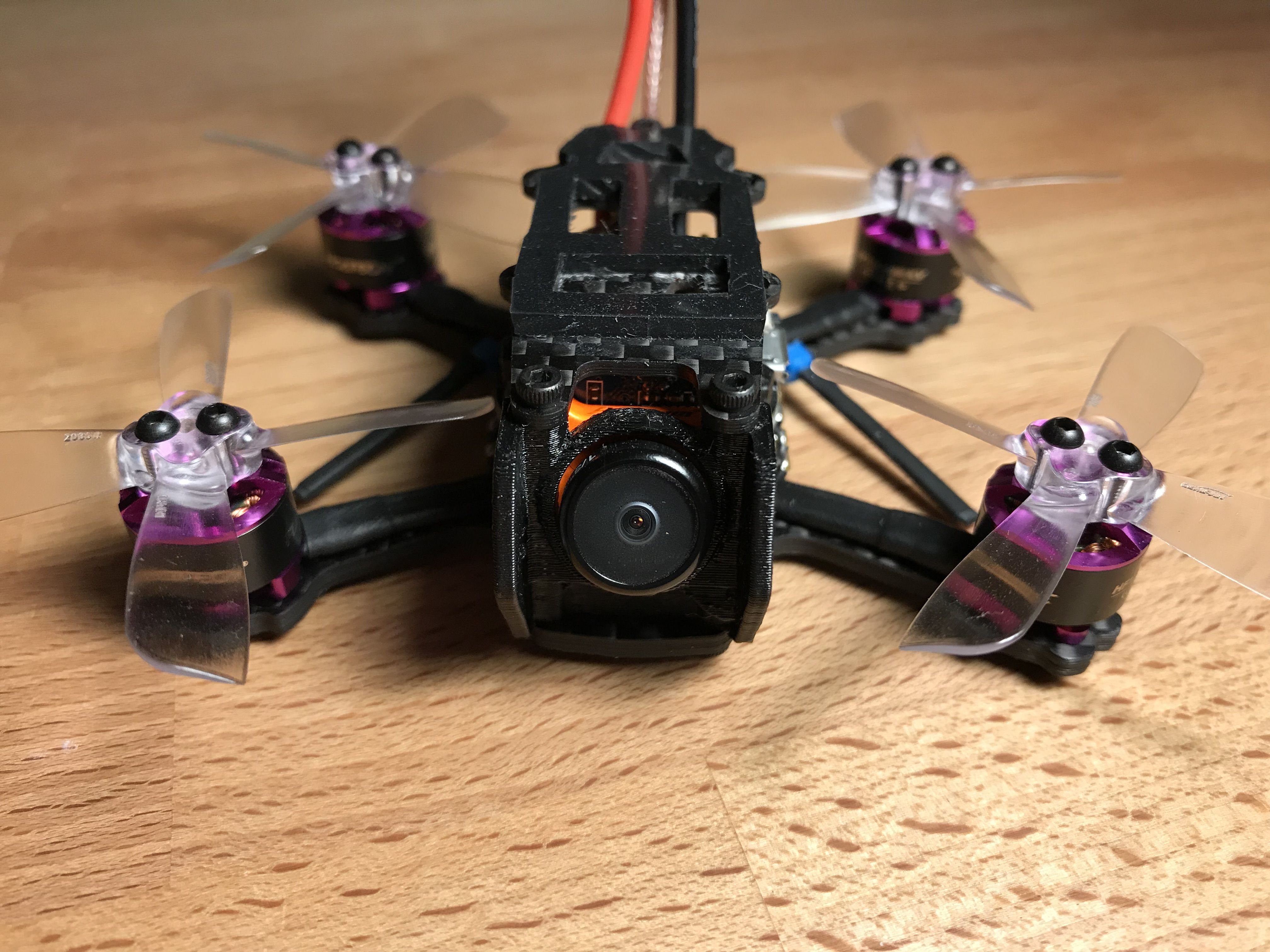
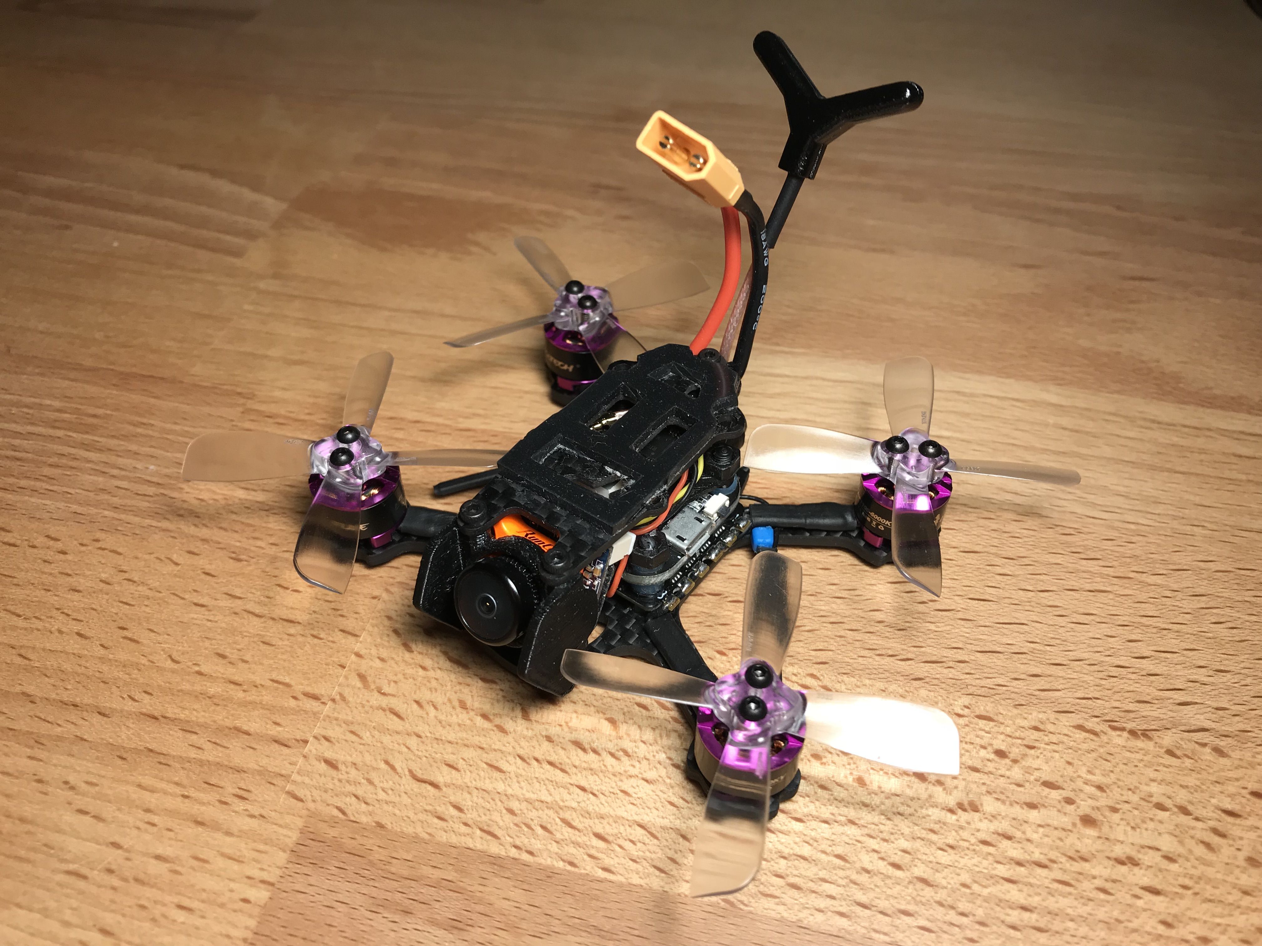
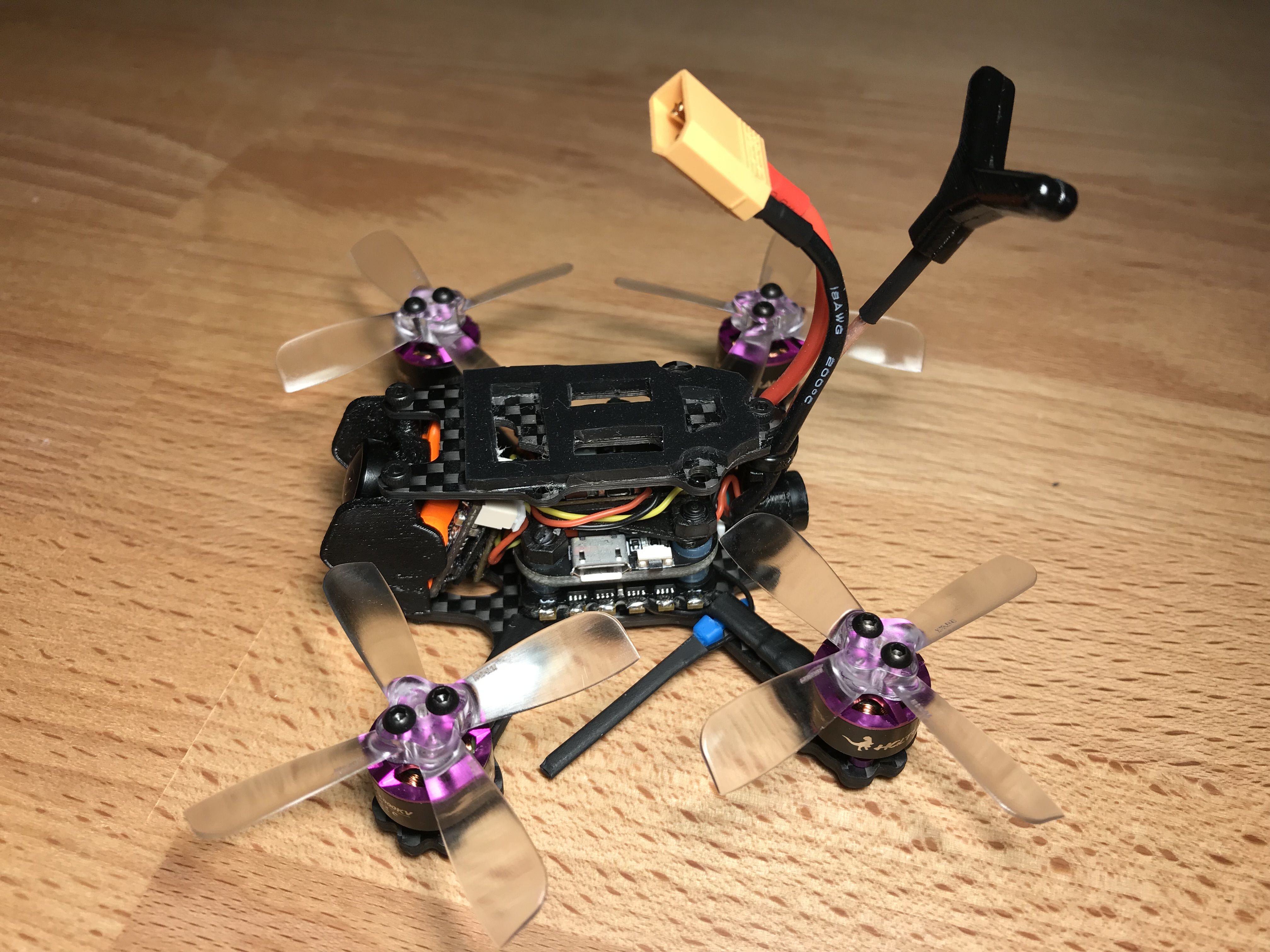
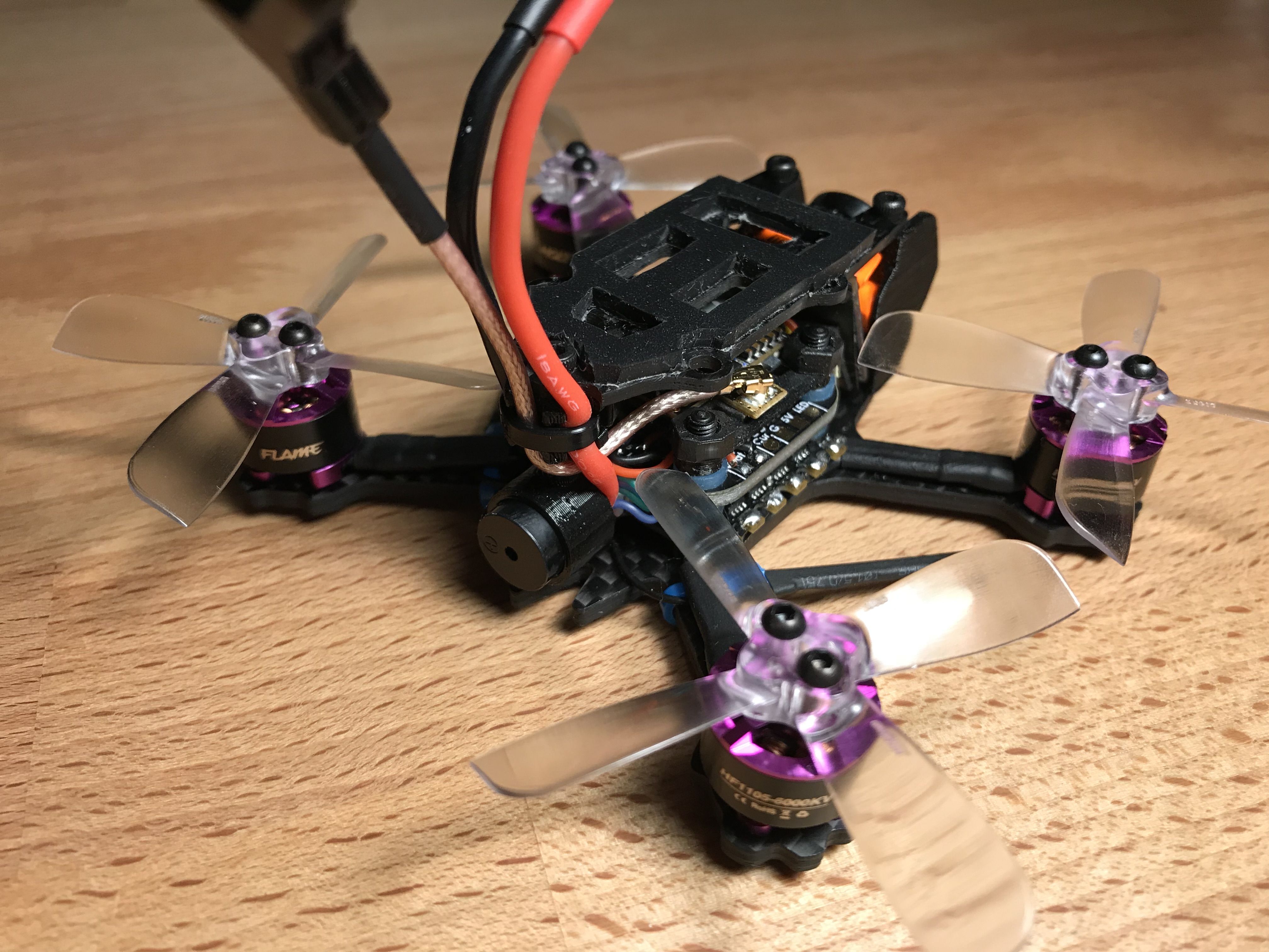
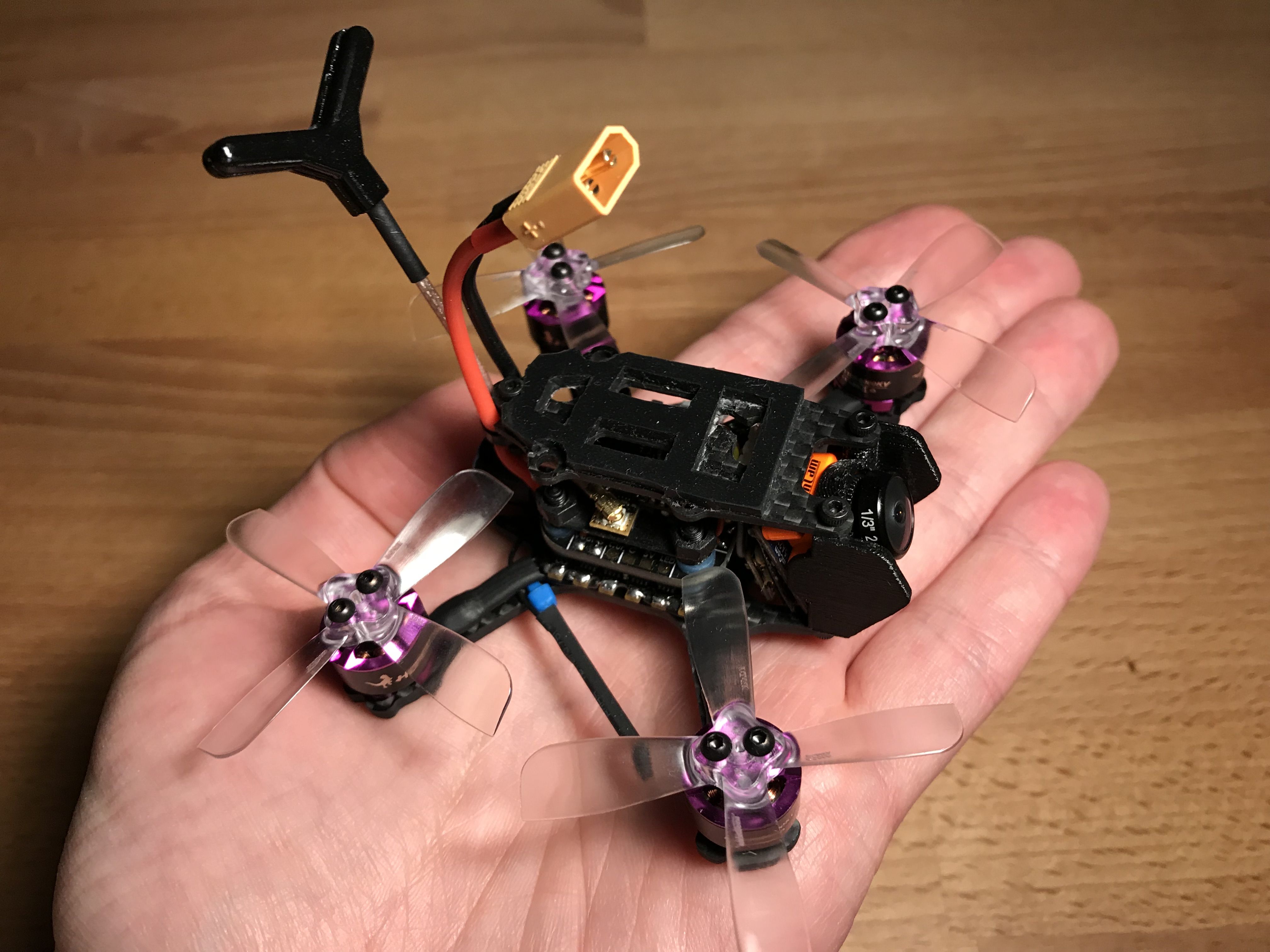
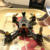
Some Family Pictures to Draw Your Attention
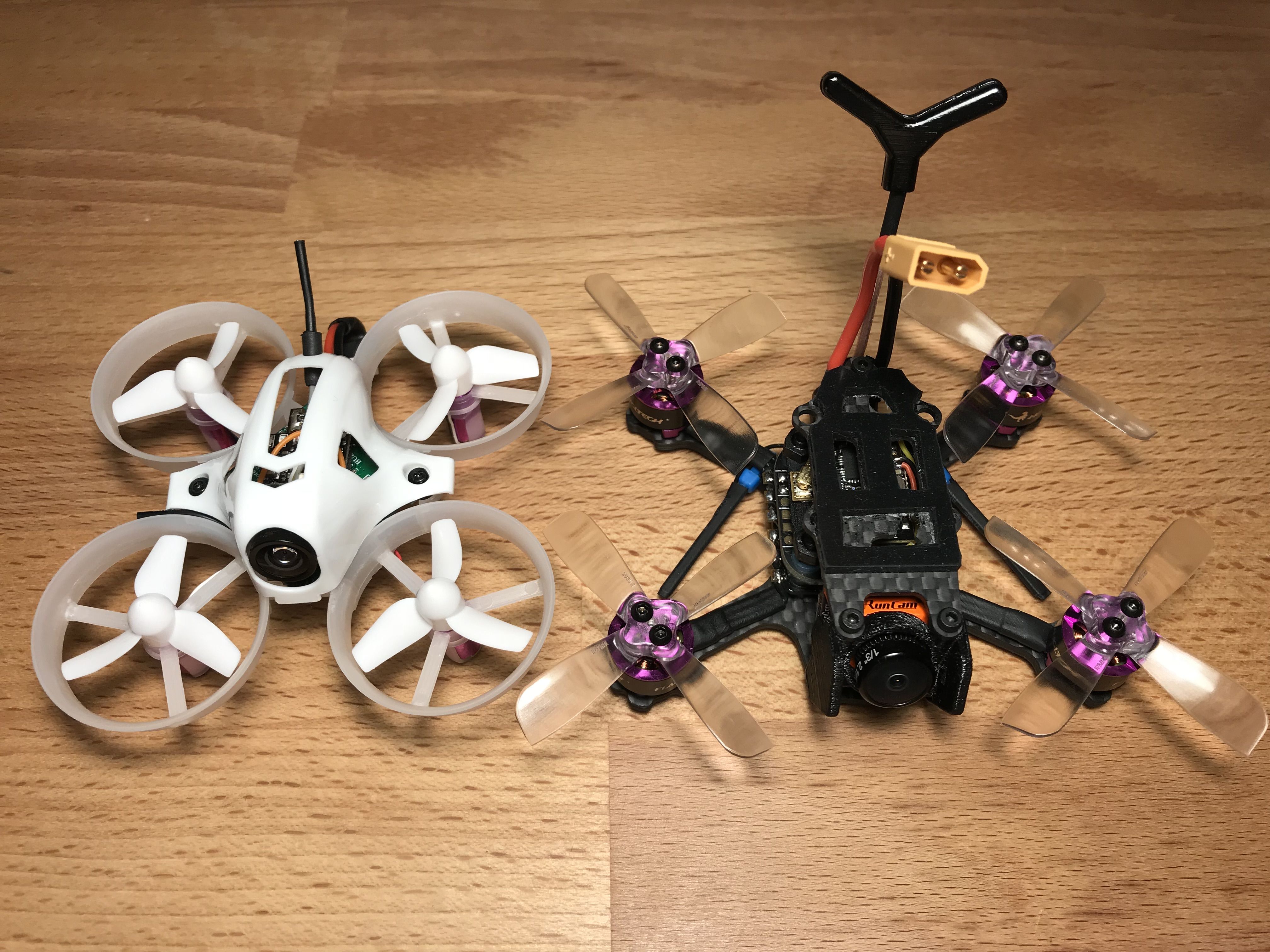
Doesn't she look cute?
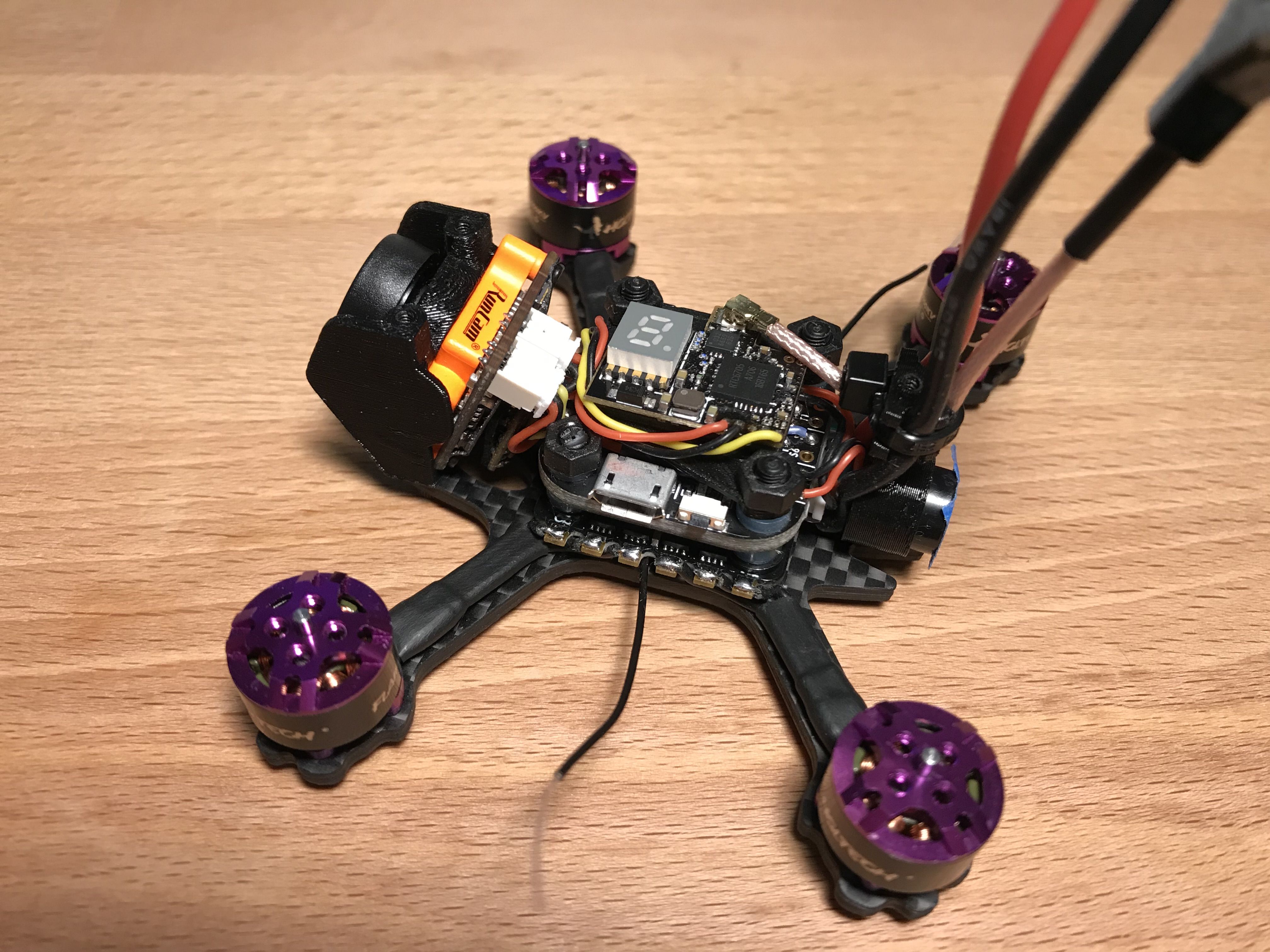
Highlights of the Build
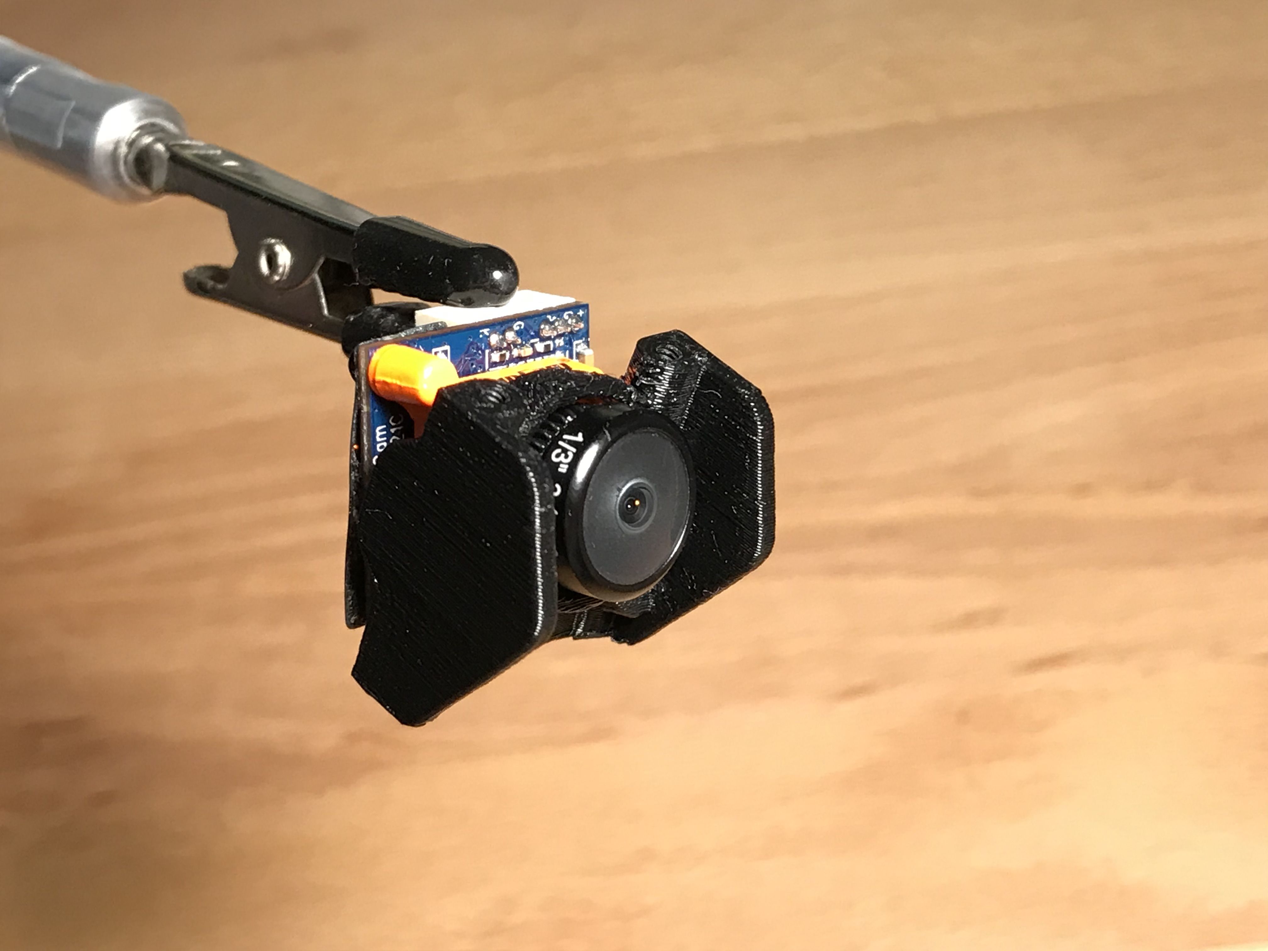
- Runcam Micro Sparrow wired for FPV camera control.
- 200mW VTX.
- Full range FrSky R-XSR receiver with Smart Port for Betaflight lua scripts.
- 1105 motors.
- Runs on 3S.
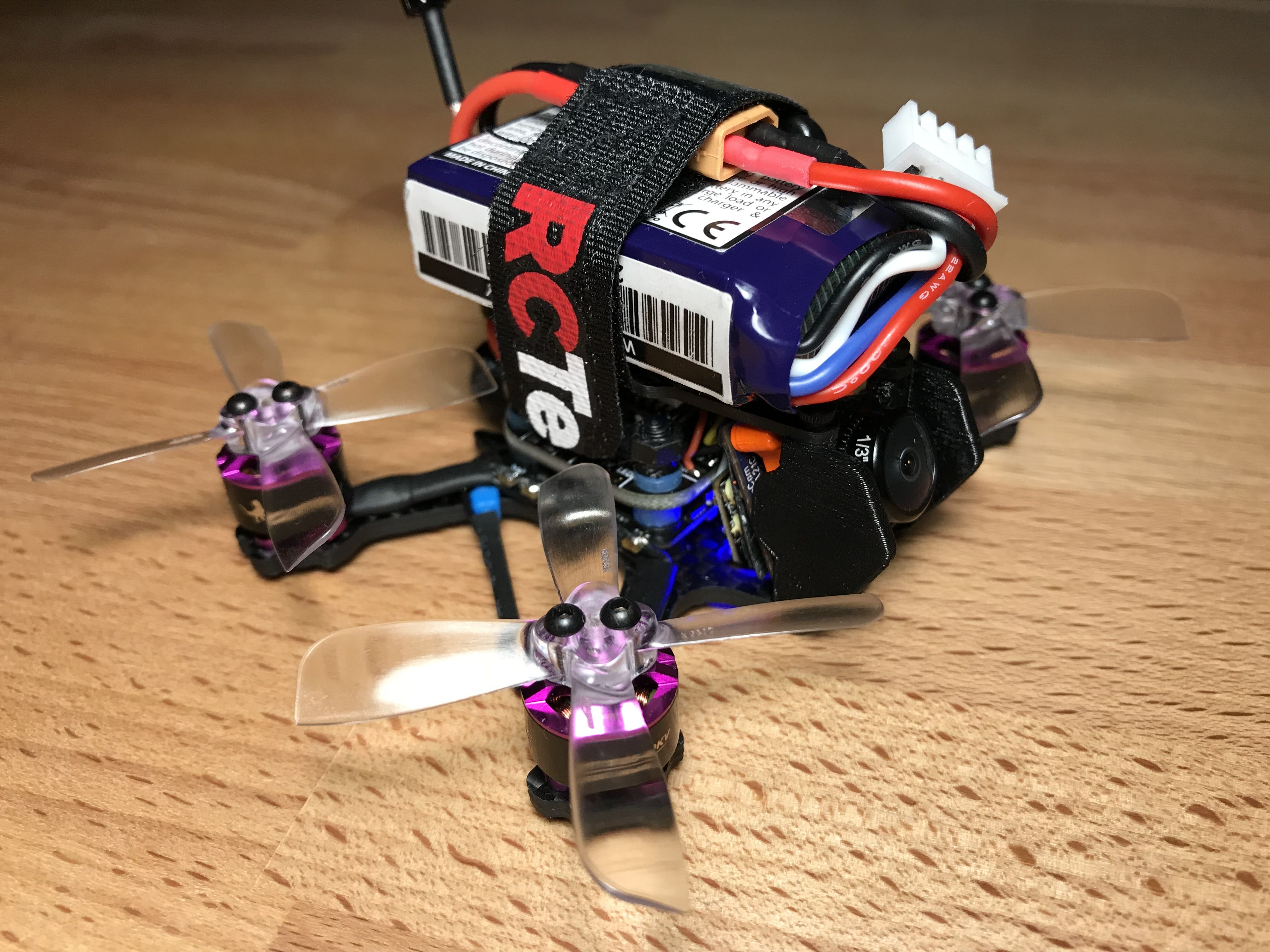
- Top-mounted battery for better CoG positioning.
- Equipped with a buzzer.
- No props in the camera view.
- Very tight build.
Things That Did Not Work out Well
I have tried other components on the way, so here is something to avoid if you are considering a similar build:
- Cheap CMOS cameras for extremely poor brightness change handling. I miss the microphone though.
- DYS BE1104 motors for low quality bearings causing vibrations.
- Omnibus F4 NANO Flight controller for a sensitive ICM 20608 gyro giving crazy yaw twitches.
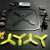
Preparations
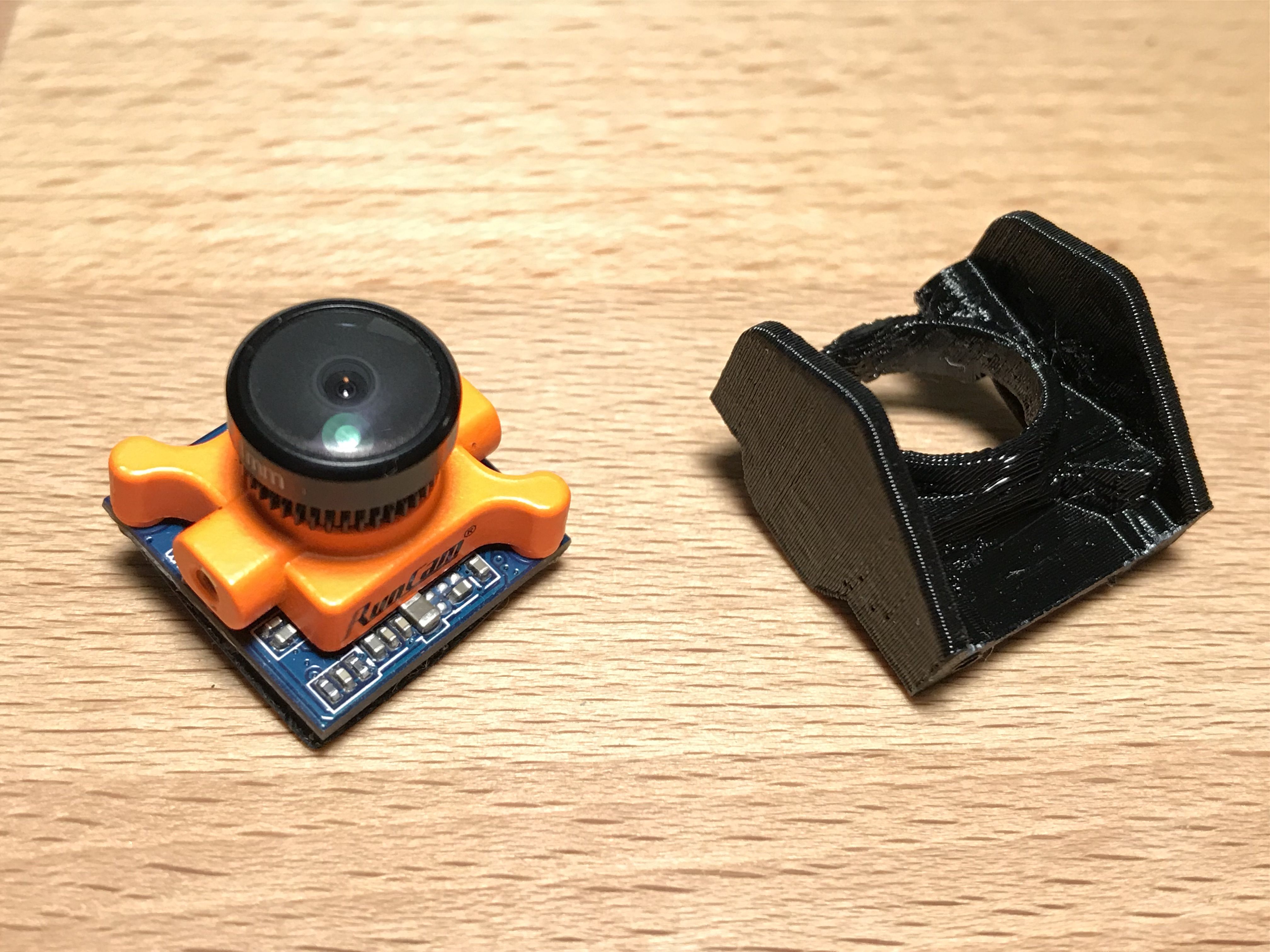
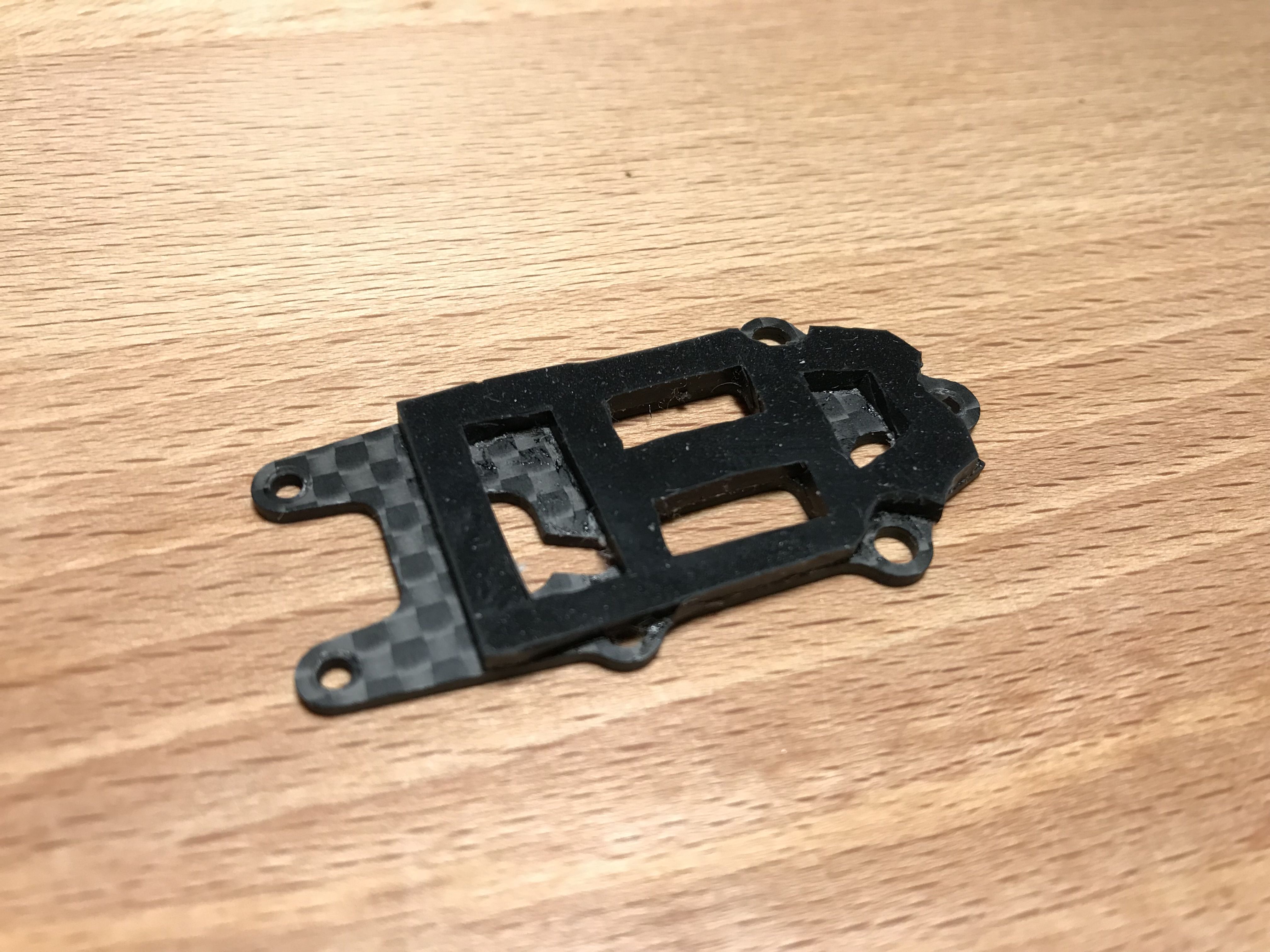
First off, you need to print the X2 Elf hardware kit. It includes a camera pod, a rear standoff and a VTX mount. I prinited mine in PETG for increased strength, but PLA will probably do as well.
Next, there are some component modifications to be made in order to fit everything into the frame.
-
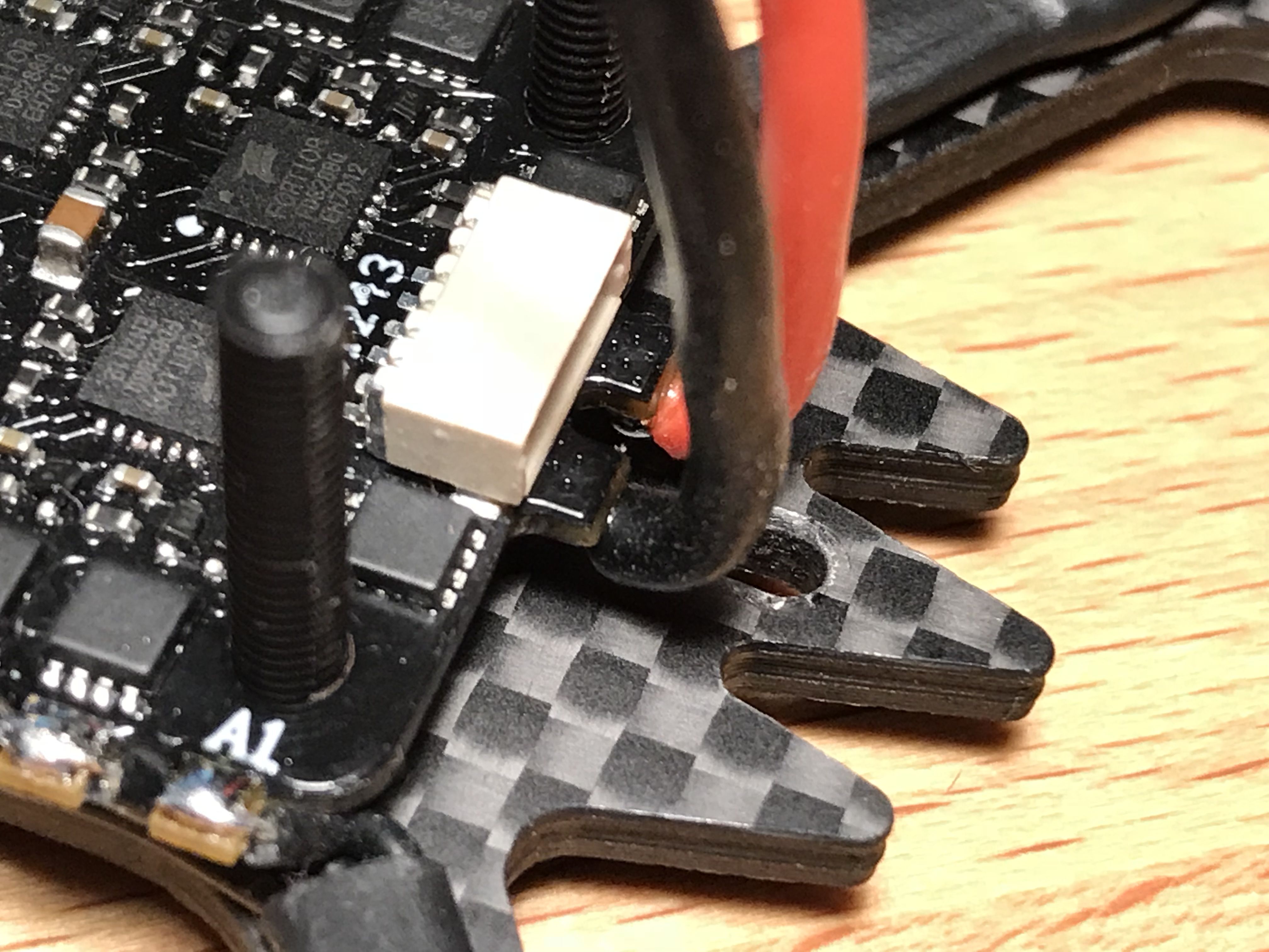
The ESC has M2 mounting holes which need to be drilled to fit M3 screws. I used a mini hand drill and a round needle file instead of a drill bit to widen the holes. I do not recommend using the actual drill bits and electrical tools since it is very easy to damage the board that way.
- The R-XSR receiver has a bulky connector socket which needs to be removed. I used flush cutters to break the housing piece by piece and desoldered the pins afterwards. It makes sense to flash the receiver with the latest firmware while it still has the connector on.
Last, I just hated the look of those rubber band tabs at the sides of the bottom plate, so I cut them off with a file. Be sure to wear respiratory protection gear if you decide to do that.
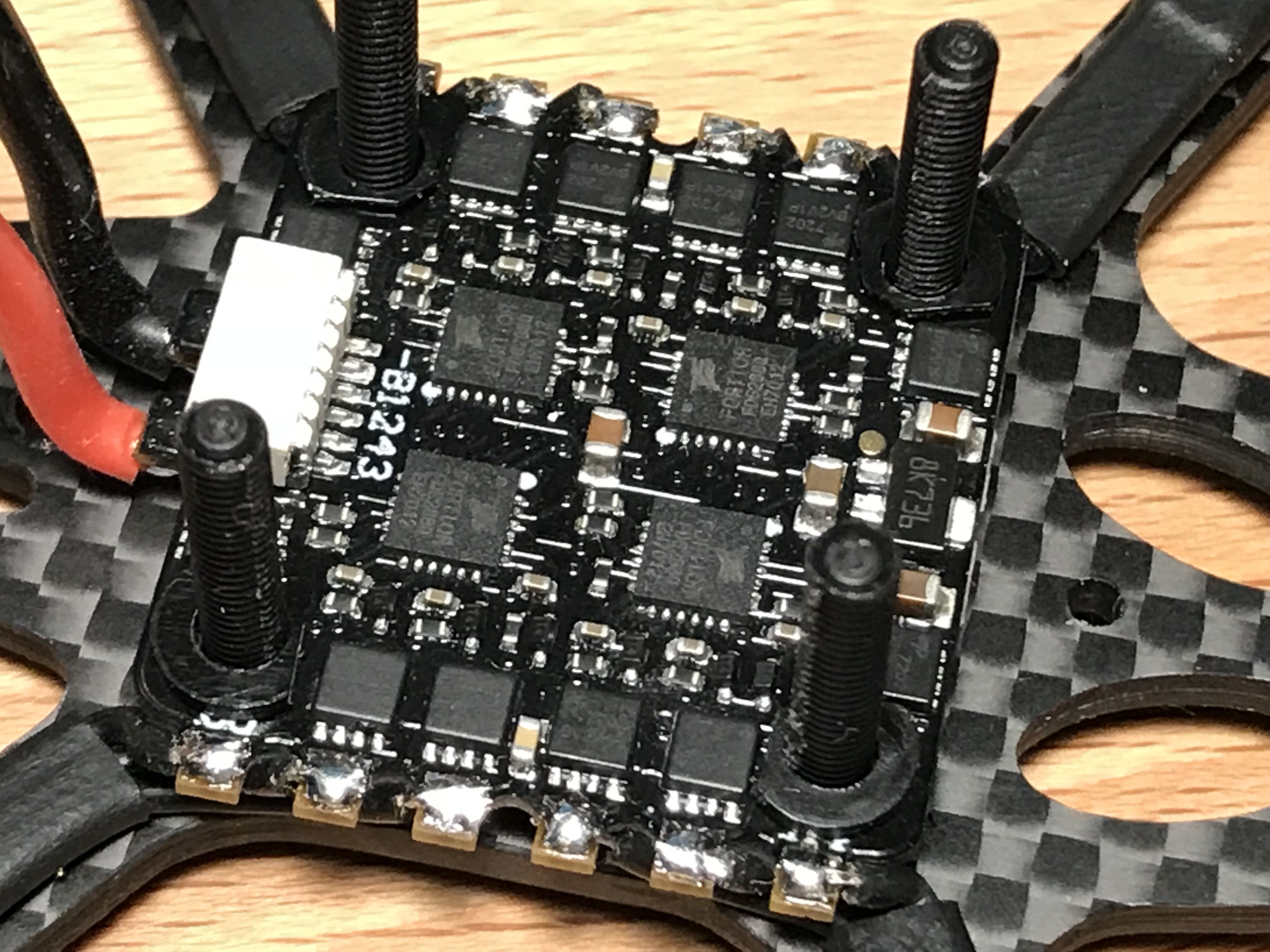
Assembling the Drivetrain
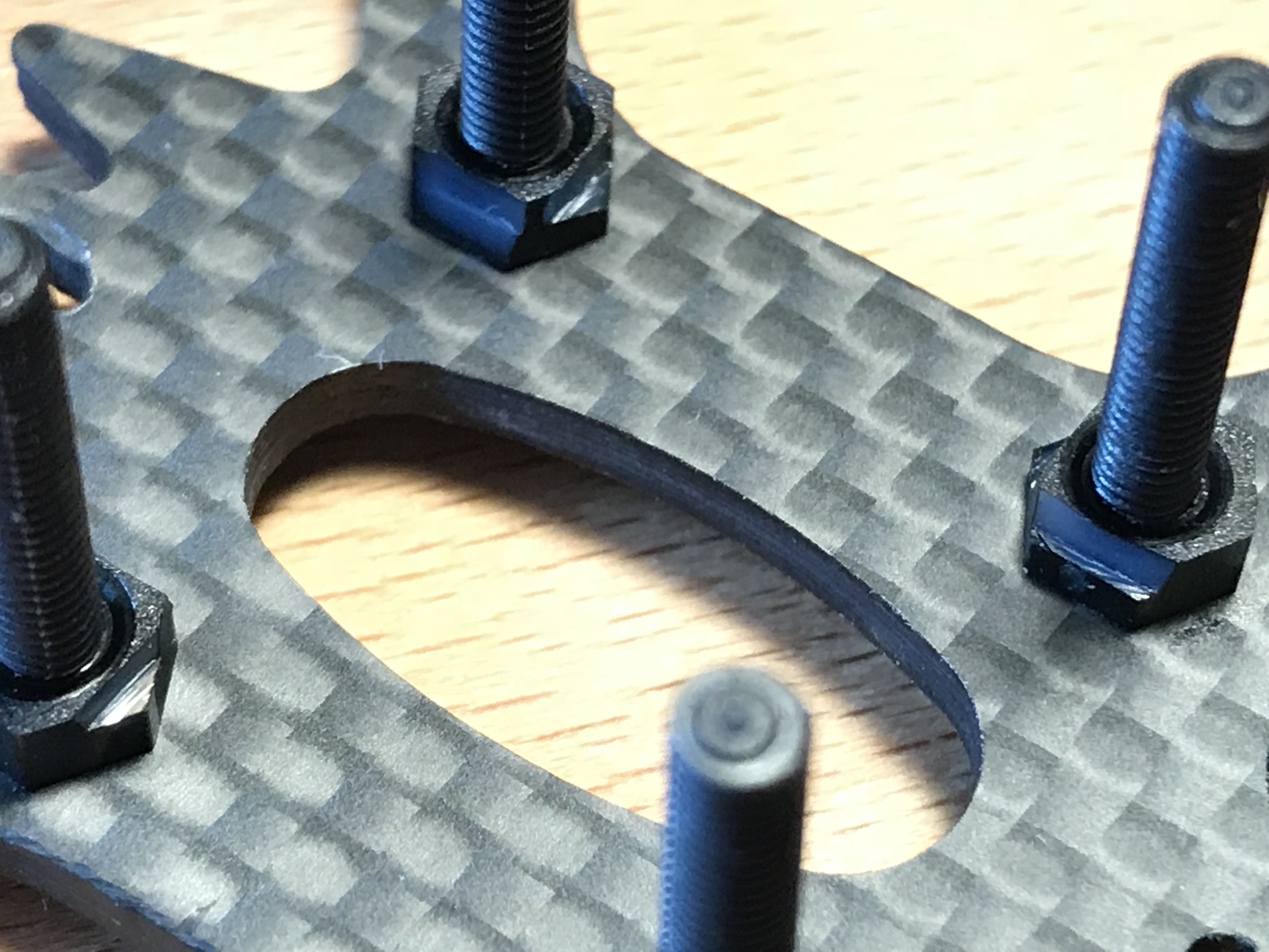
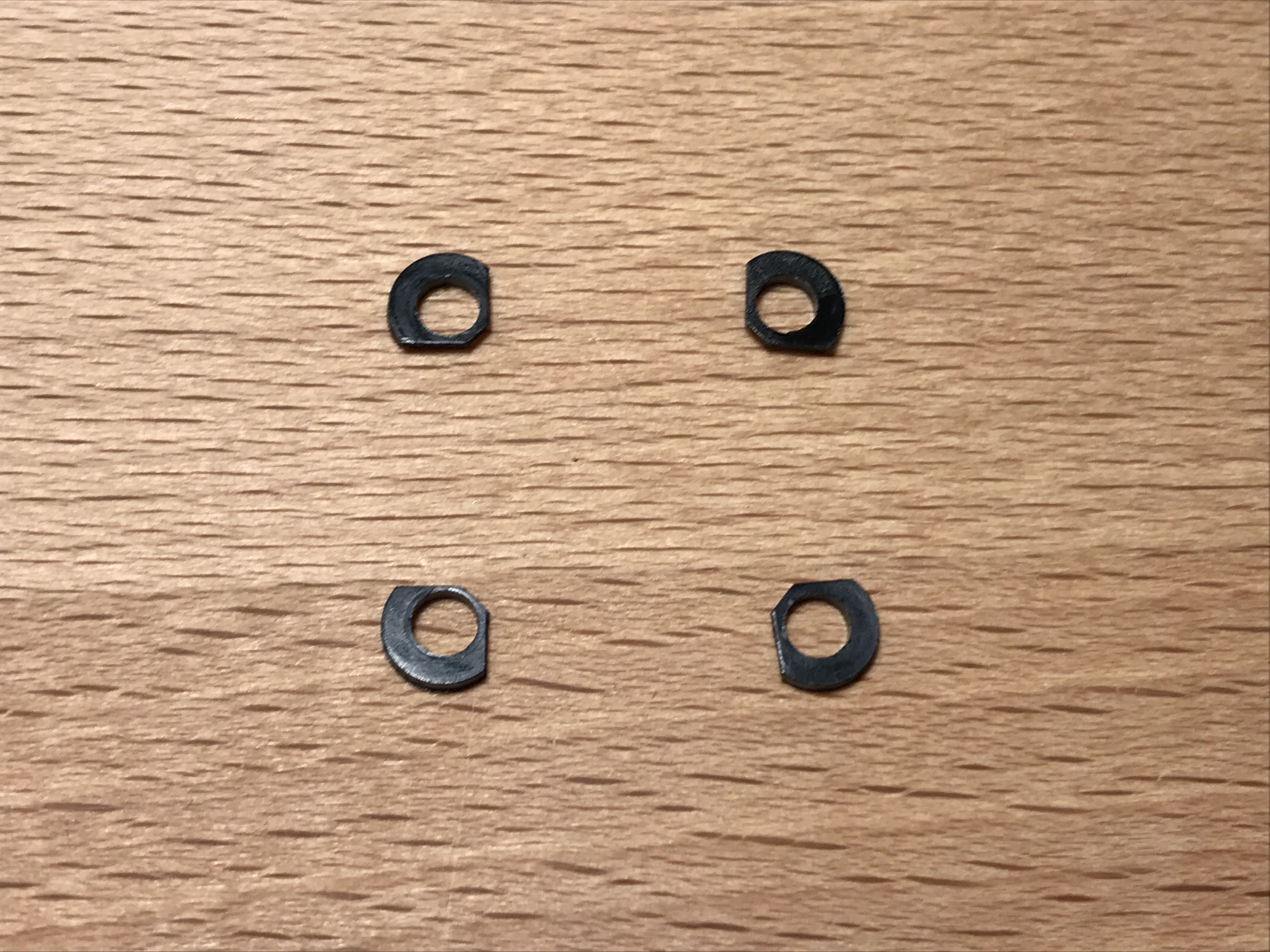
Put 20 mm M3 nylon screws through the base plate and fix them in place with nylon nuts which will serve as spacers.
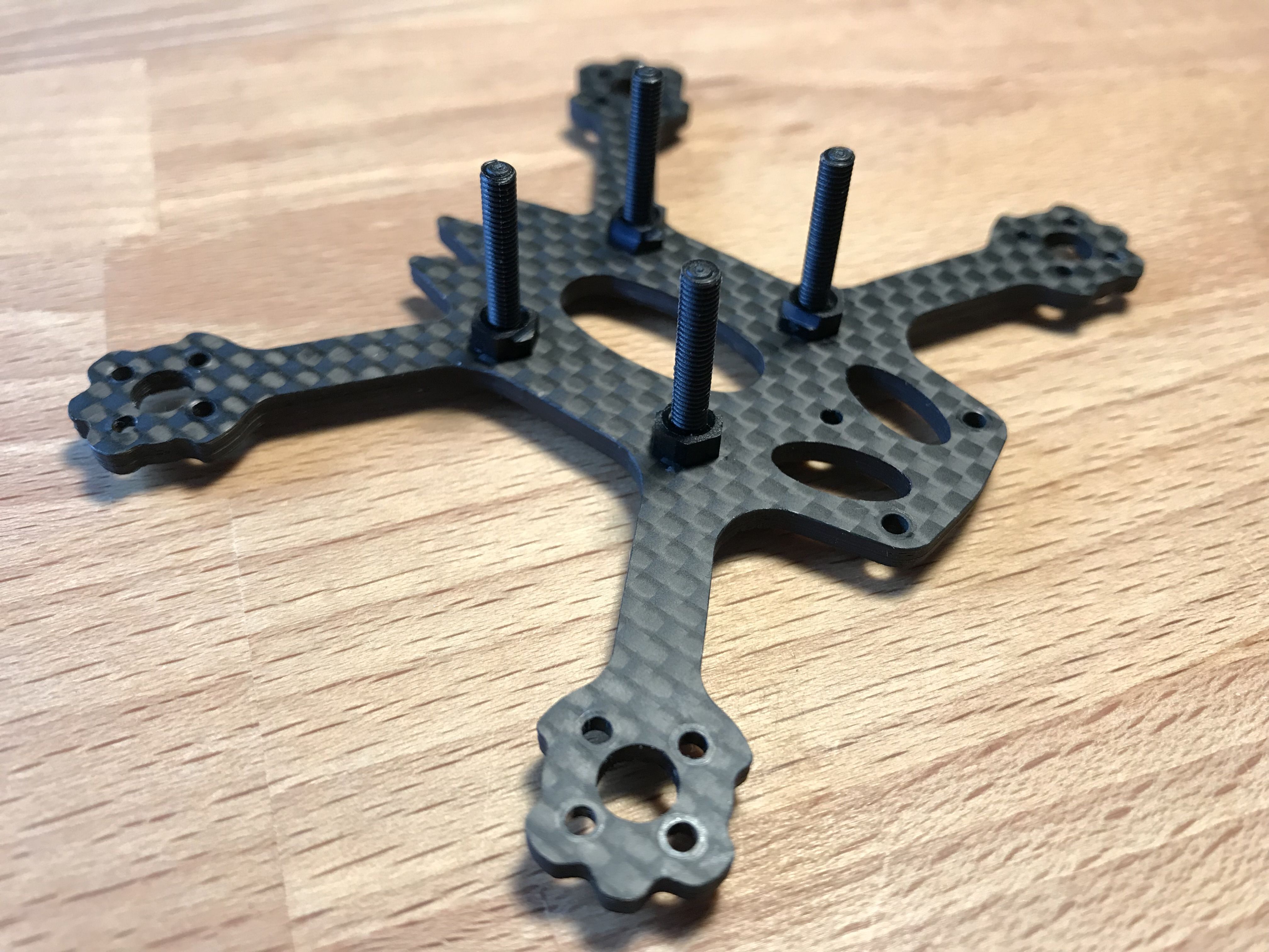
Cut off the corners of the nuts as shown and make sure the ESC goes all the way down. Also check that no components on the ESC are touching the frame. Add nylon washers otherwise.
Desolder the lead wires from the ESC, cut off the rigid portions close to ends where they were soldered at, bend the ends to a 90 degree shape, pre-tin and solder them back so the wires go straight up. This is necessary to provide enough clearance for the rear standoff.
Screw the motors in place, align the wires and route them between the ESC motor pads. Cut the wires to length leaving a bit of slack. Make sure you leave enough wire for the ends to be stripped and soldered to the ESC. Also measure the length of heatshrink tube needed for motor wires protection.
Undo the motor screws, put the heatshrink on, shrink it, put the motors back (don't forget to put some loctite on the screws) and solder the motor wires.
Use a mulimeter to check the wiring and the assembly:
- There should be no continuity between positive and negative battery leads. Check the soldering otherwise.
- There should be no continuity between any motor pad on the ESC and the frame. Check the motor screw length otherwise, most likely some screw is touching the windings inside the motor.
- There should be continuity between all ESC motor pads within one motor group when the motor is connected. The opposite means the winding in the motor is damaged.
The drivetrain is complete.
Wiring the Flight Controller
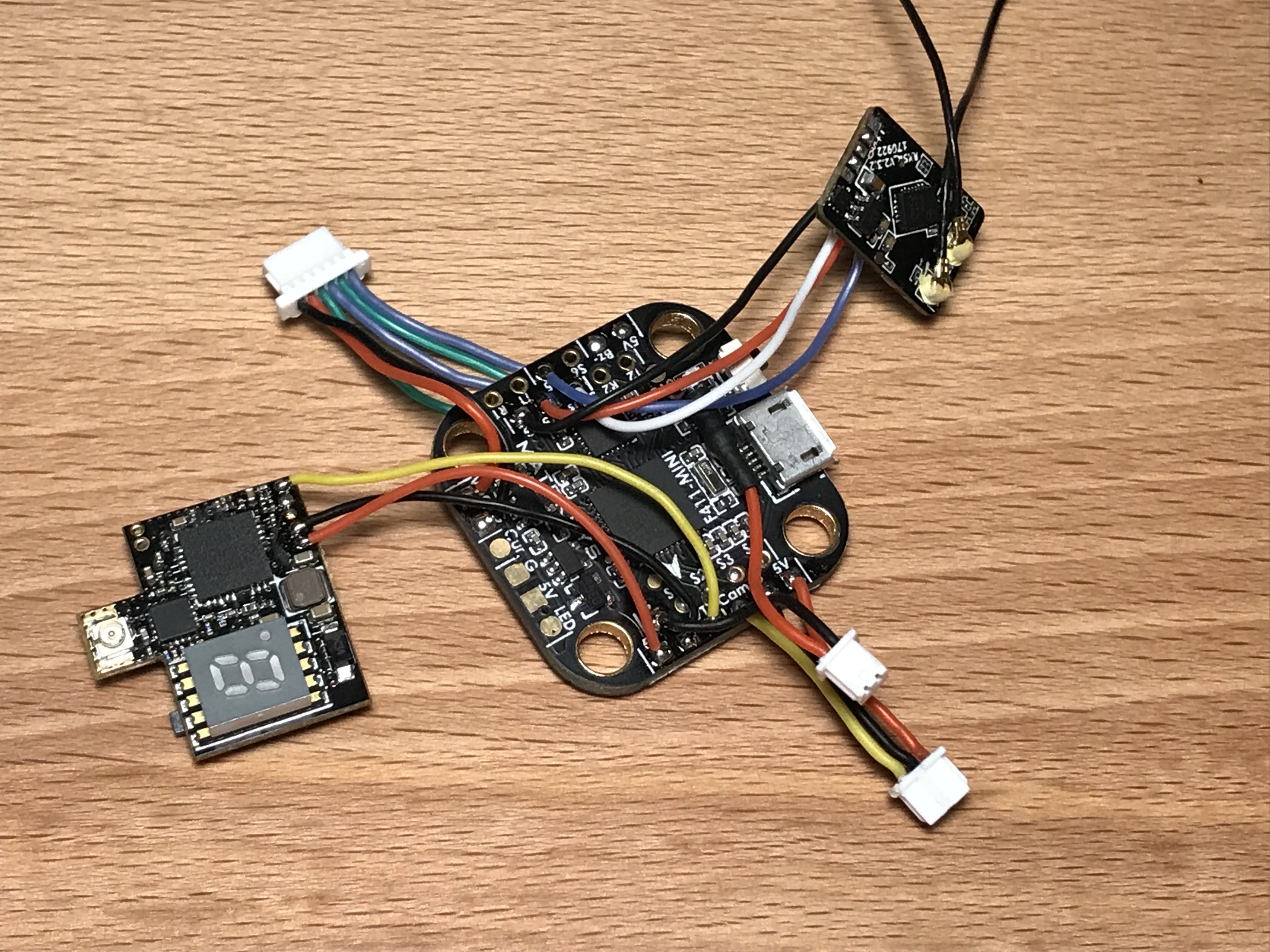
You will need these parts to wire the flight controller:
- Three pin 1.25 mm pitch JST-XH female connector for the Runcam that came with the camera.
- Two pin 1.25 mm pitch JST-XH female connector for the Runcam OSD. It did not come with the camera, so I took the housing from a pigtail set and replaced the wires with the nice silicone ones that came with the camera.
- A 220 Ohm resistor for FPV camera control. Got it from a resistor kit.
- ESC signal wire with a six pin 1.25 mm pitch JST-XH female connector. Came with the ESC.
- 30 AWG silicone wires of different colors.
- Four 1 mm nylon washers for extra clearance between the ESC and the flight controller.
Fit the camera into the pod so you can temporarily screw it in place to measure the wire length. The pod has small protrusions where normally the screws holding the camera should go, so the camera should just click in place.
Put the silicone spacers that come with the flight controller into the flight controller and slide it on top of the ESC. Use 5 mm M2 steel screws to attach the pod with the camera to the bottom plate. Do not use longer screws as they could come into contact with the camera's PCB and ruin it.
Now, with the flight controller and the camera in place you can measure the wires' length.
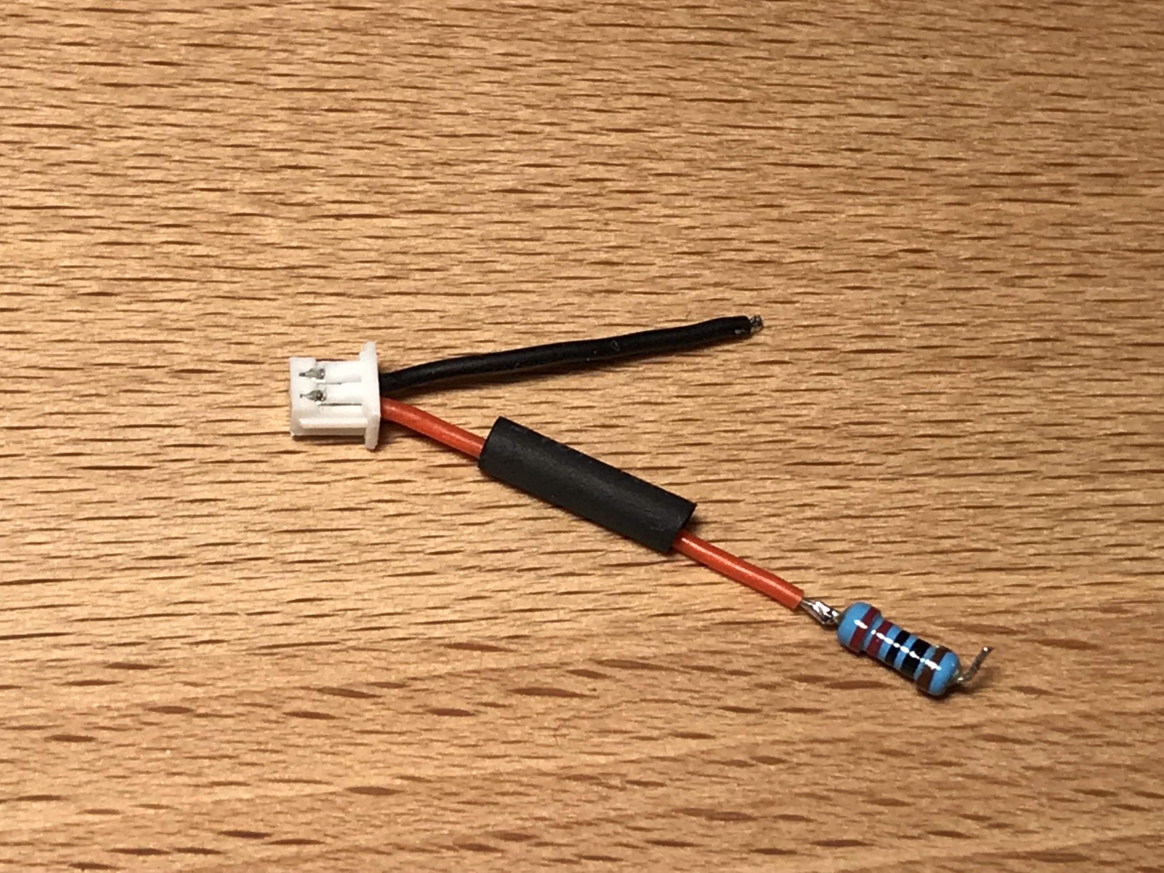
Camera Control Cable
It should connect the RSSI pad of the flight controller through the 220 Ohm resistor to the OSD pin of the camera (red wire), and the ground pad near the signal pads on the flight controller to OSD ground on the camera (black cable).
Measure the wire length, solder and heatshrink as shown.

Solder the cable:
- The resistor to RSSI pad on the flight controller.
- OSD GND pin on the camera to G pad next to S1 pad on the flight controller.
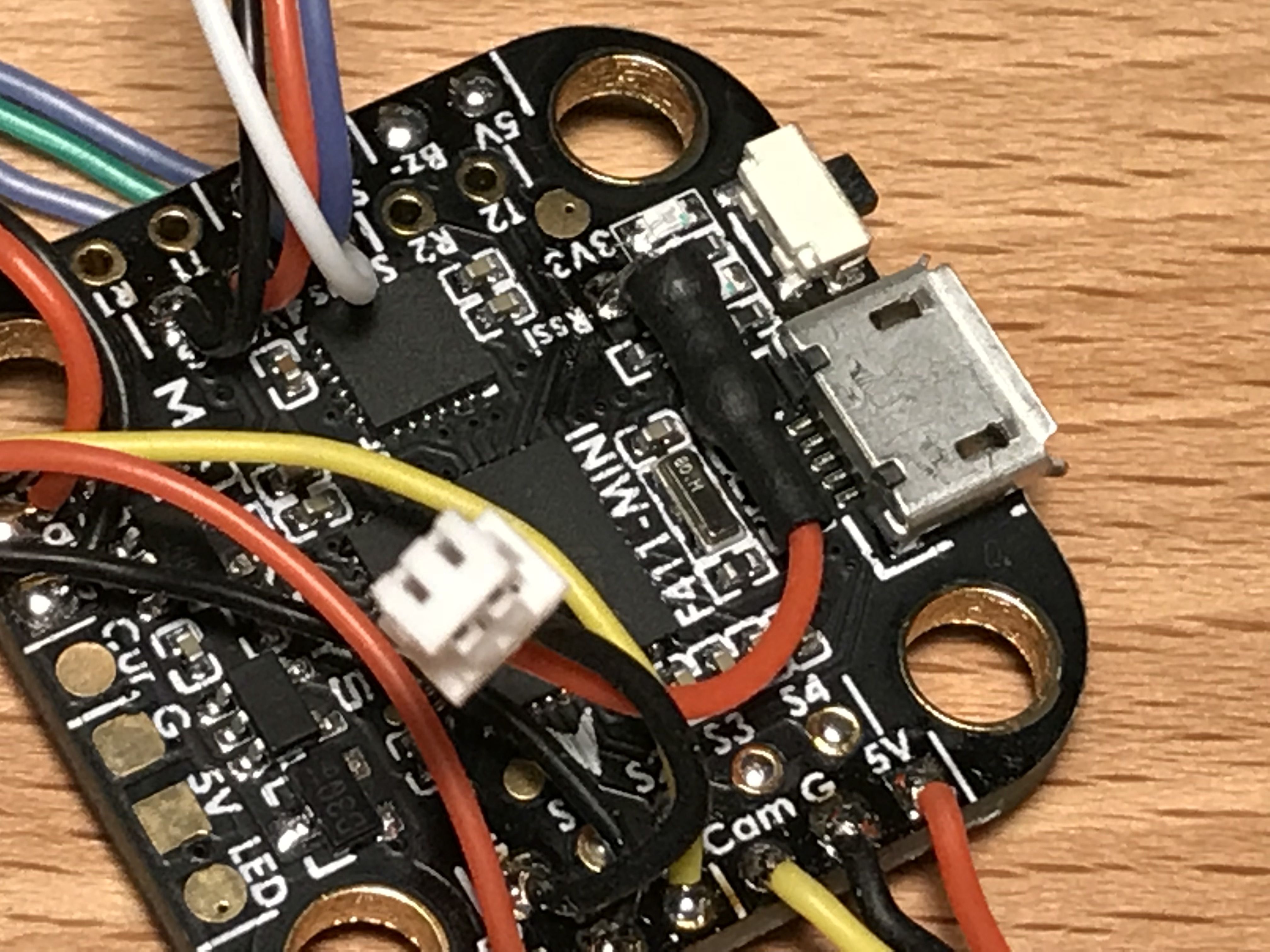
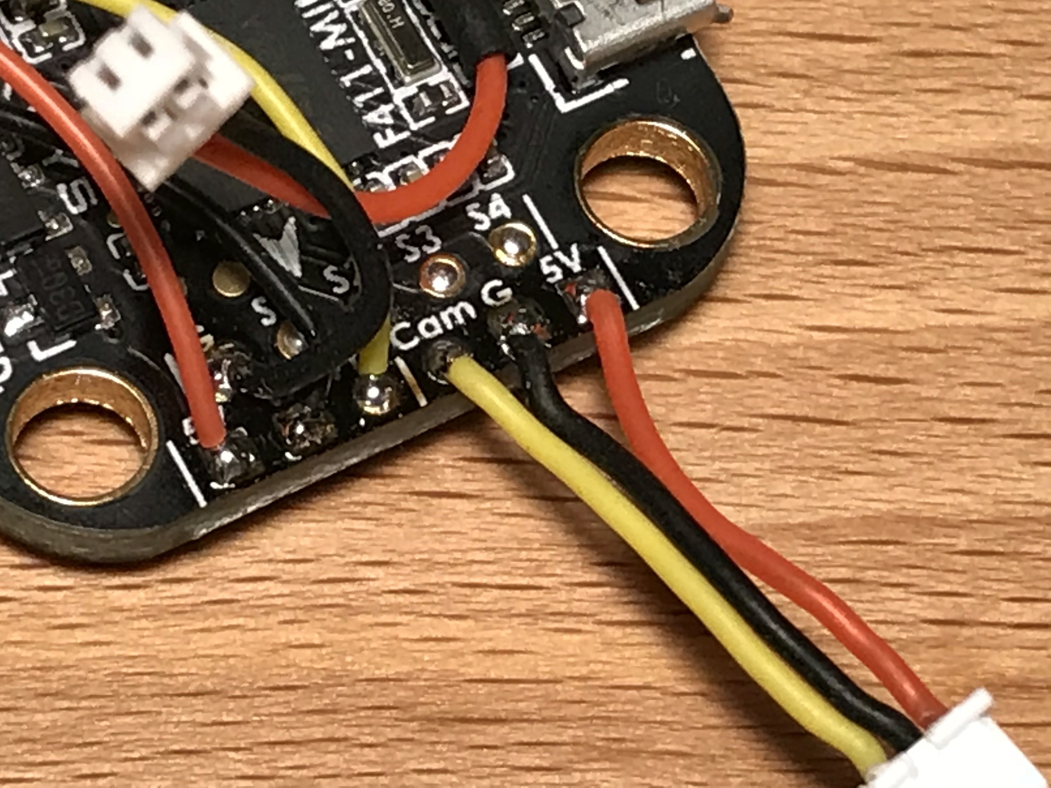
Camera Cable
It should connect the Cam, G and 5V at the front of the flight controller to the camera.
Cut the wires to length and solder as shown.
- Cam on the flight controller to Video on the camera.
- G on the flight controller to GND on the camera.
- 5V on the flight controller to 5-36V on the camera.
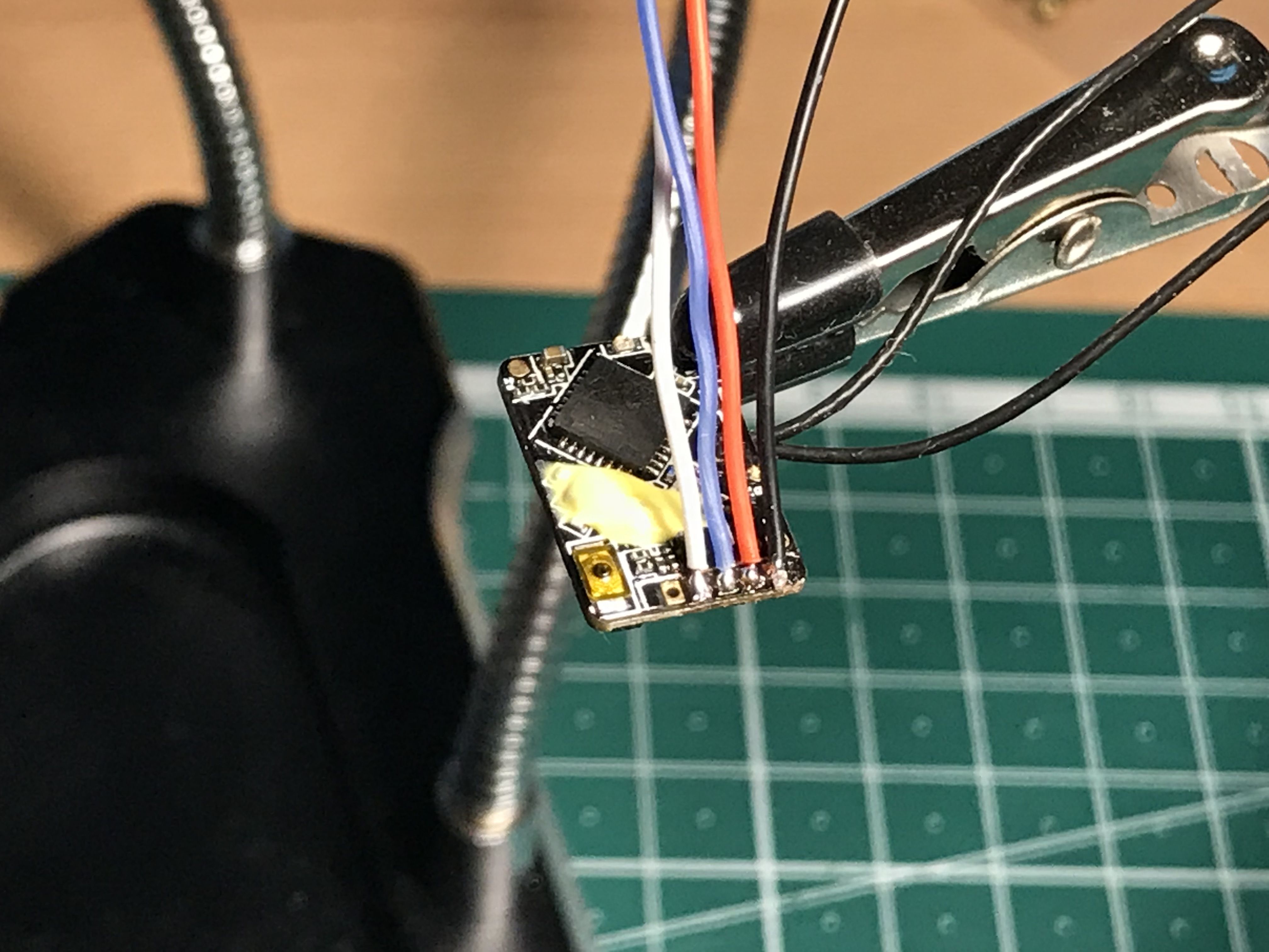
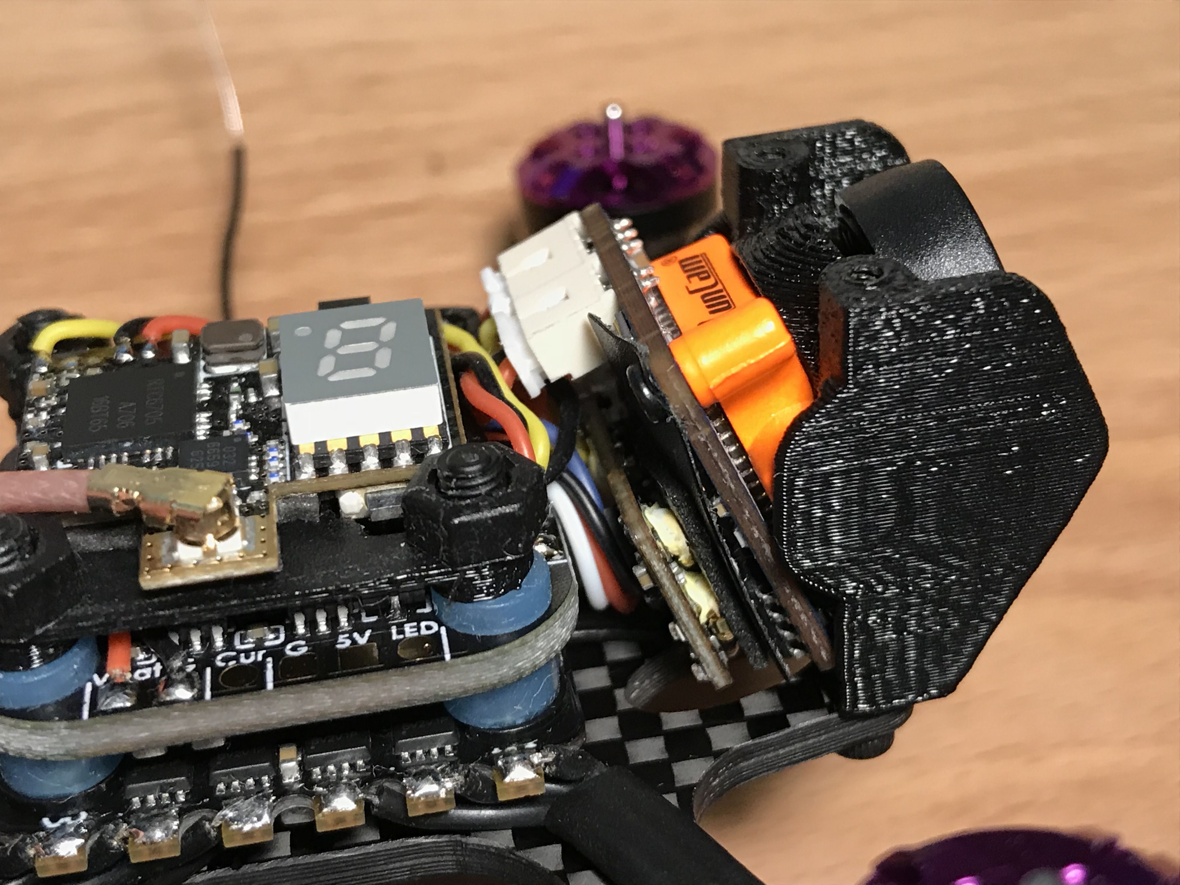
Receiver
The receiver will be placed between the camera and the flight tower (yep, that's tight).
Solder the wires to the receiver as shown.
- Black to GND.
- Red to +5V.
- Blue to S.Port.
- White to SBUS_OUT.
Put the receiver between the camera and the flight tower, thread the wires on top of the flight controller, cut them to length and solder.
- SBUS_OUT on the receiver to SBUS on the flight controller.
- +5V on the receiver to 4V5 on the flight controller.
- GND on the receiver to G next to 4V5 on the flight controller.
- S.Port on the receiver to S5 on the flight controller.
Never mind the rear standoff at the picture.
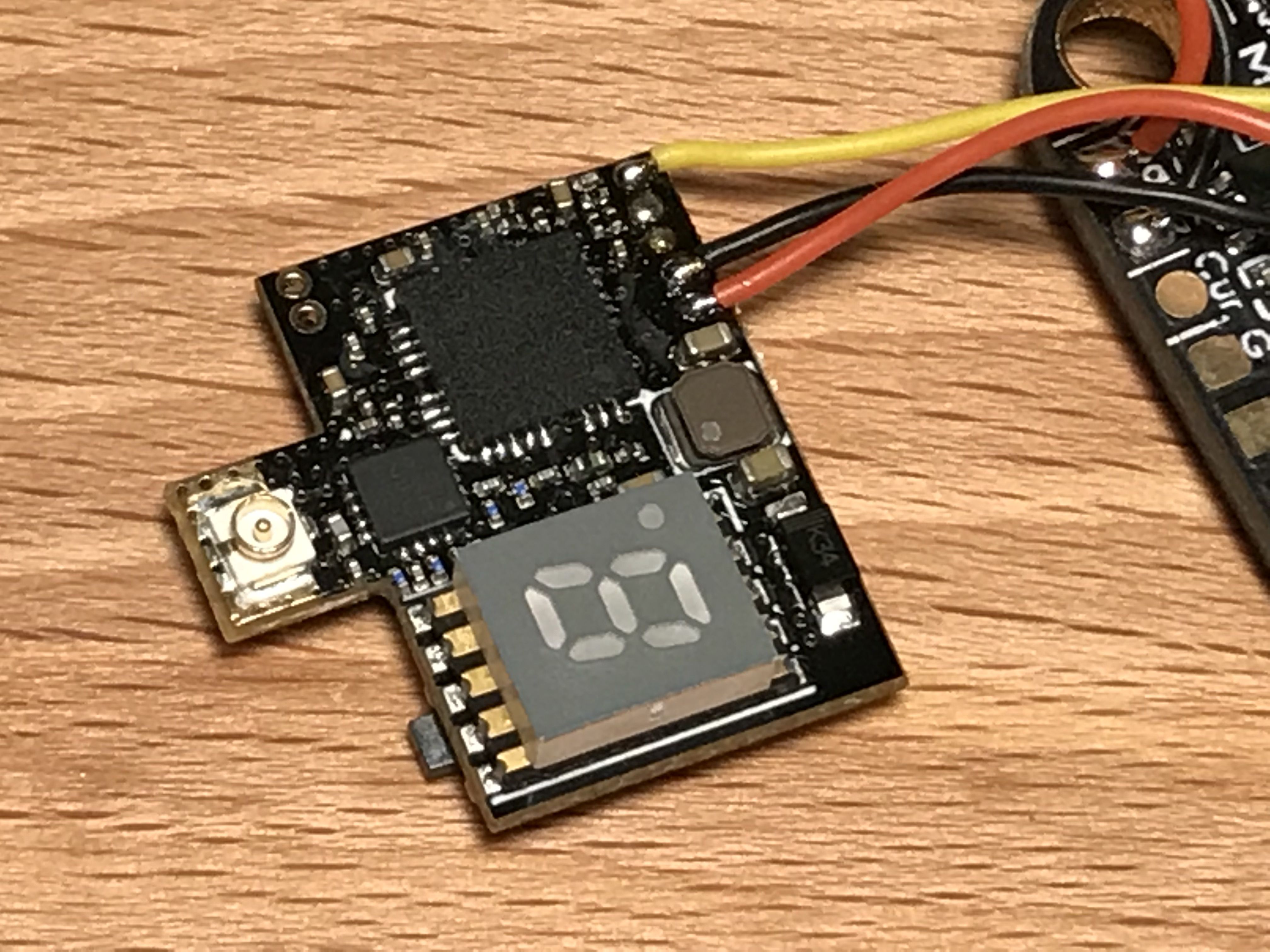
VTX
Solder the wires to the VTX.
- Yellow to Video.
- Black to GND.
- Red to 3.2-5V.
Put the 3D-printed VTX plate from the hardware kit on top of the flight controller so the button cut-out is on the right hand side of the quad, put the VTX in place and measure the wire length.
Solder the wires to the VTX group at the front of the flight controller.
- 3.2-5V on the VTX to 5V on the flight controller.
- GND on the VTX to G on the flight controller.
- Video on the VTX to VTX on the flight controller.
You should be soldering the VTX to the left part of the flight controller where the wires are covering the pad names at the picture.
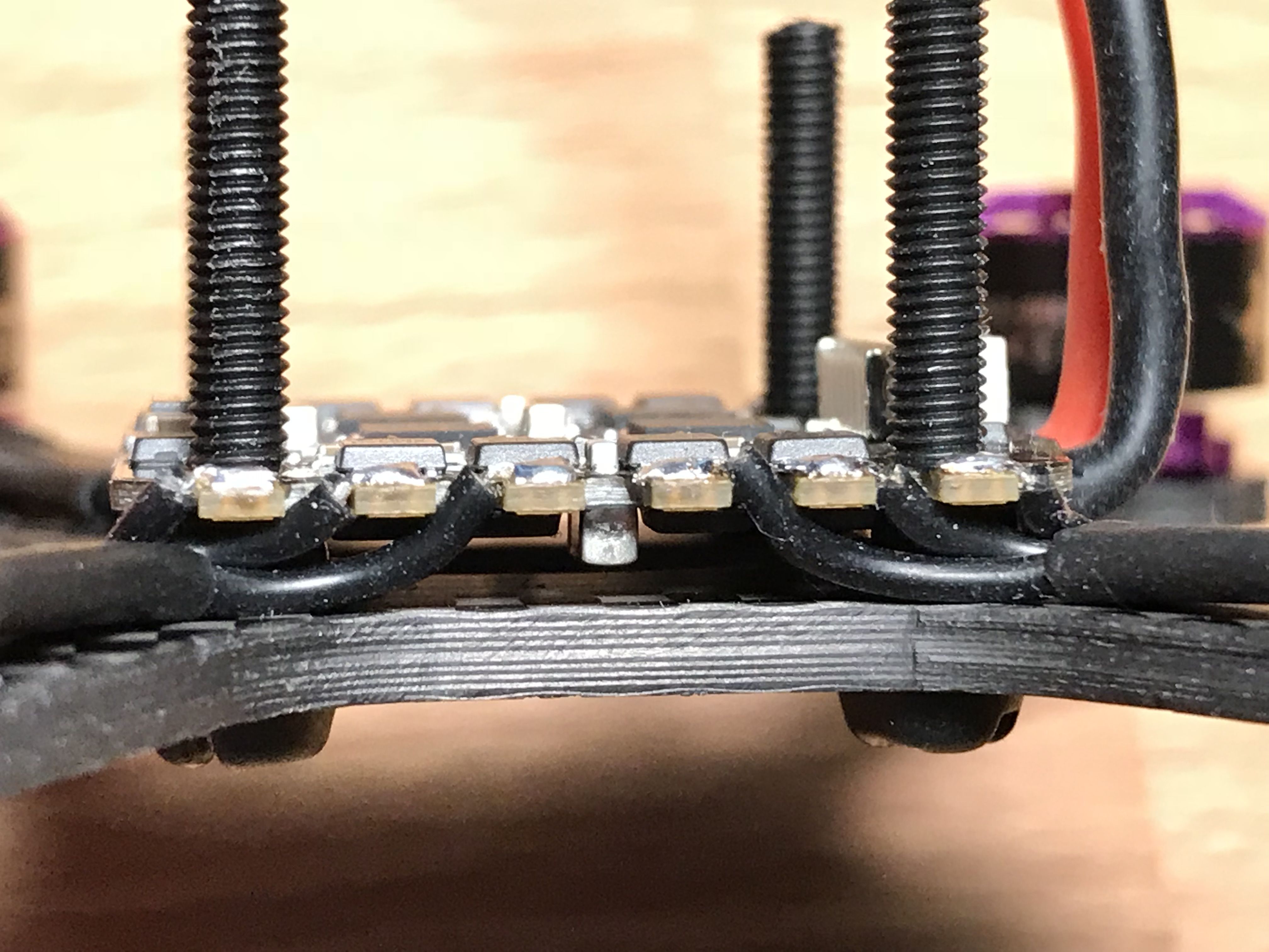
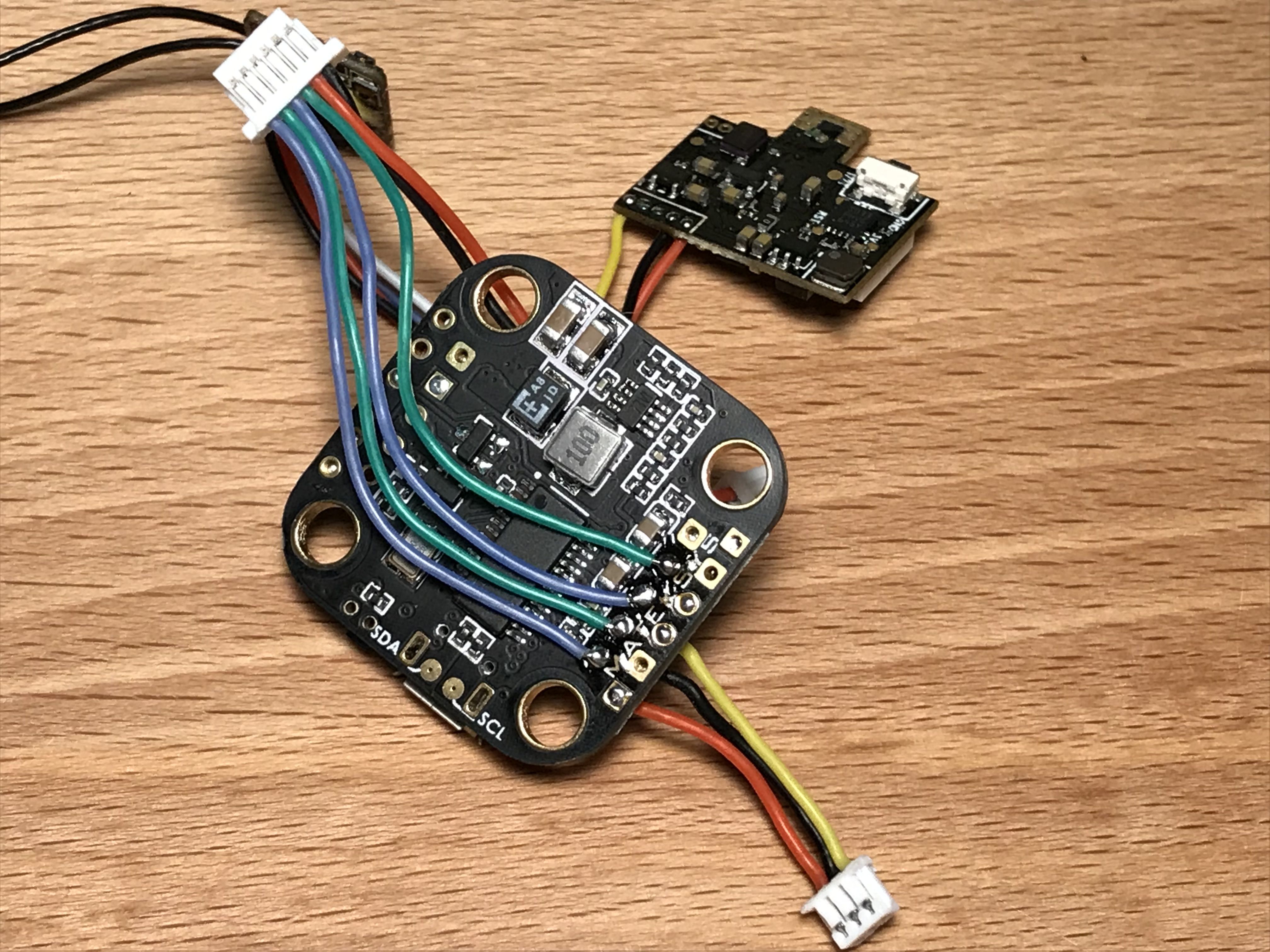
ESC Signal and Power
The ESC connector has 6 pins. Four of them are signal wires to control the motors (blue and green) and the other two are providing power to the flight controller (red and black).
Signal wires should go underneath the flight controller while power wires should go on top. Plug the connector into the ESC, cut wires to length, unplug the connector and solder the wires.
Power wires:
- "-" on the ESC to G next to Vbat on the flight controller.
- B on the ESC to Vbat on the flight controller.
Signal wires:
- 1,2,3,4 on the ESC to S1, S2, S3, S4 on the bottom side of the flight controller.
Buzzer Pads
Pre-tin the buzzer pads (5V and Bz-) at the back of the flight controller so it will be easier to solder the buzzer wires later on.
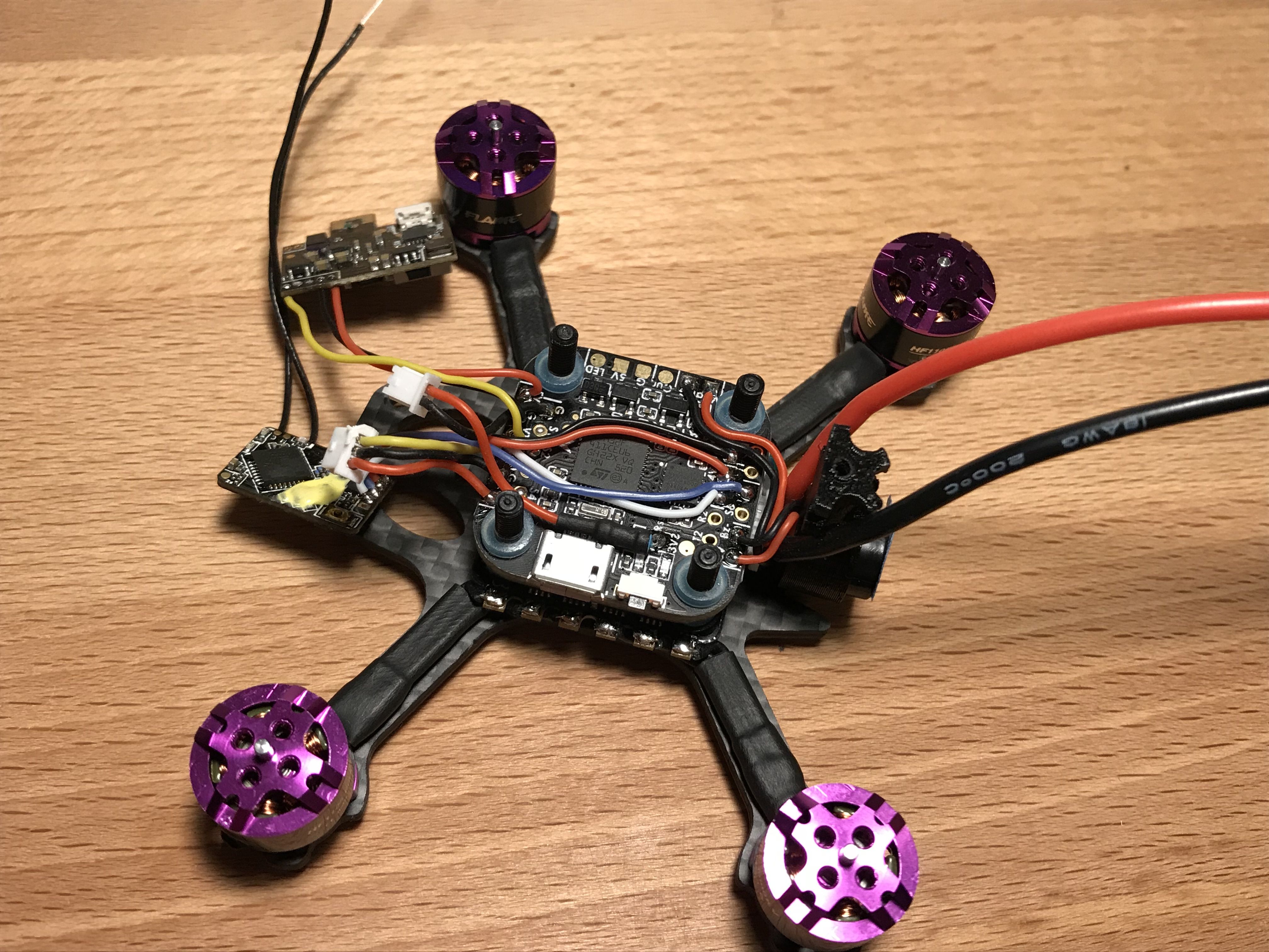
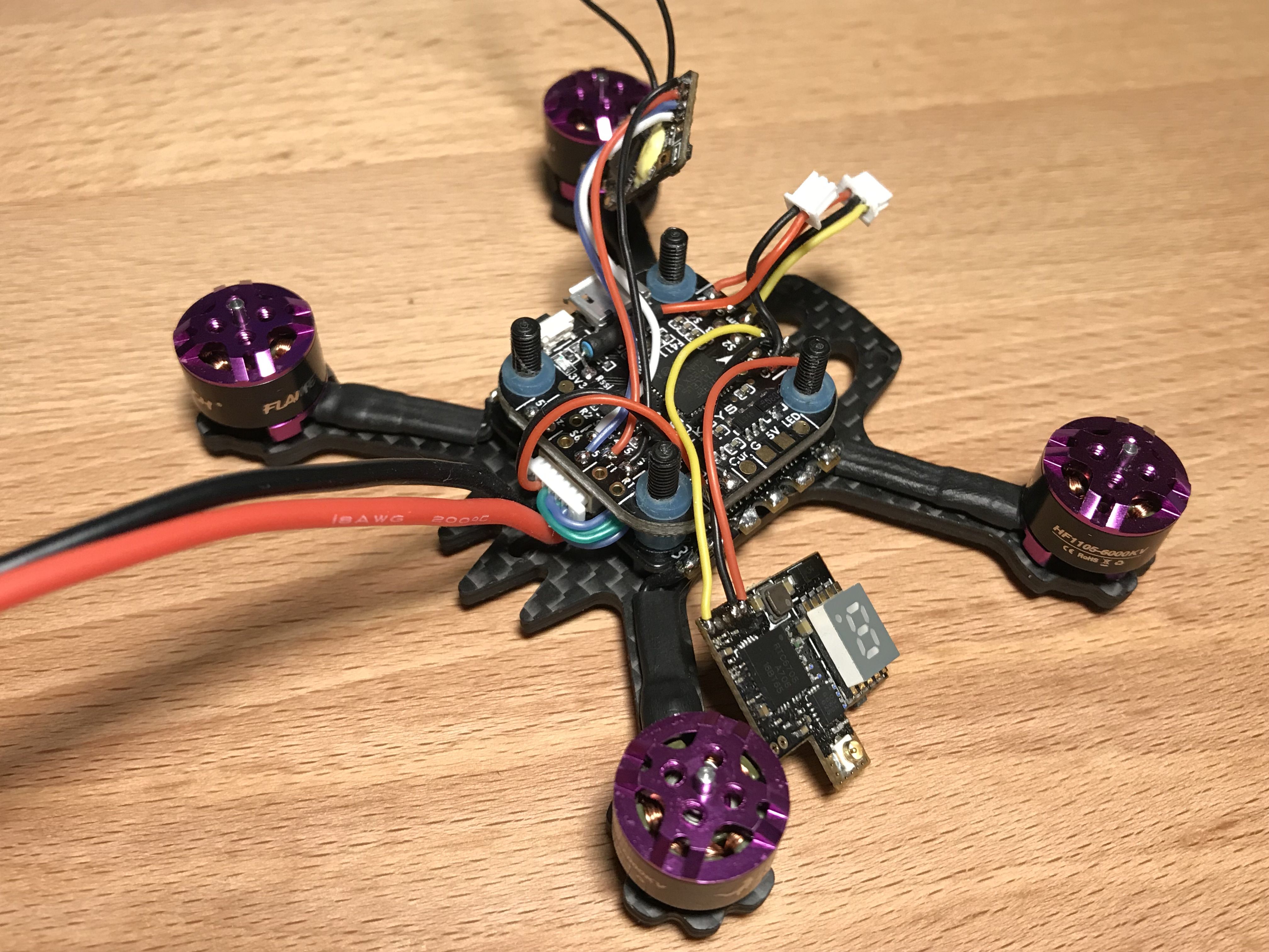
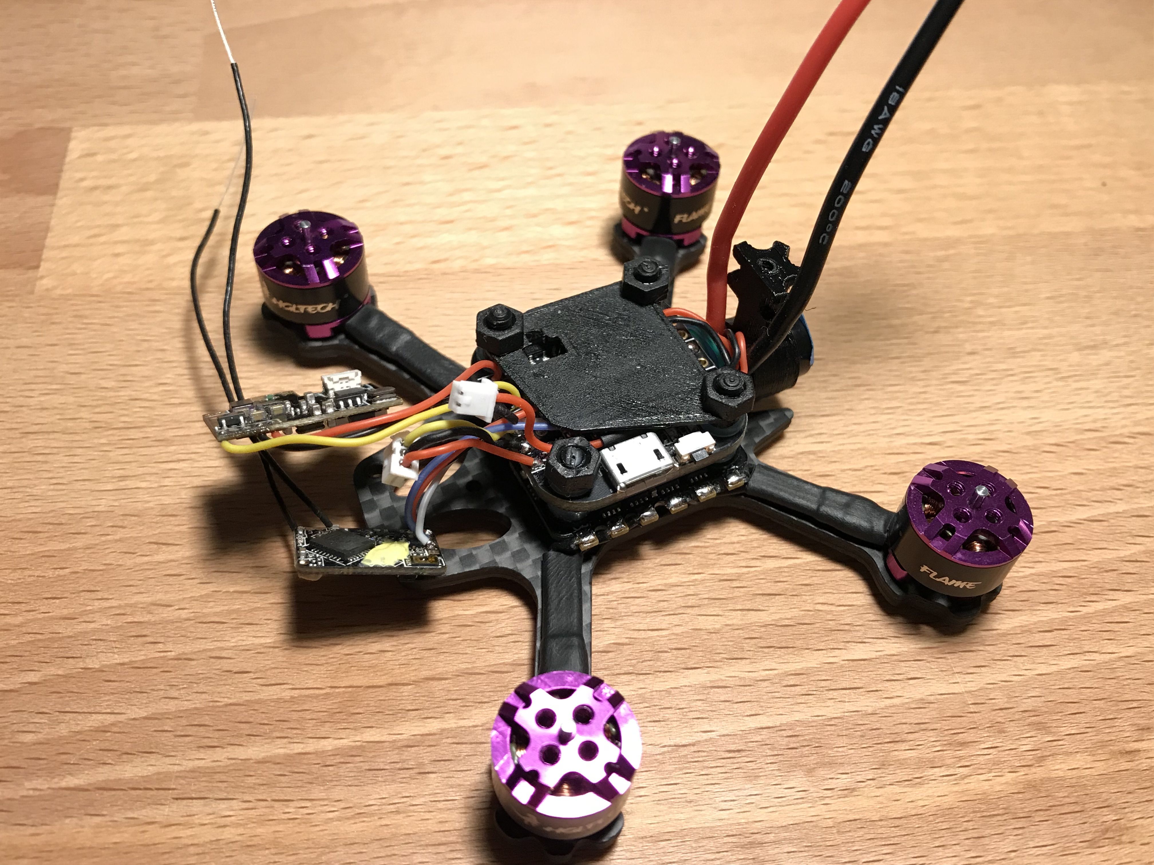
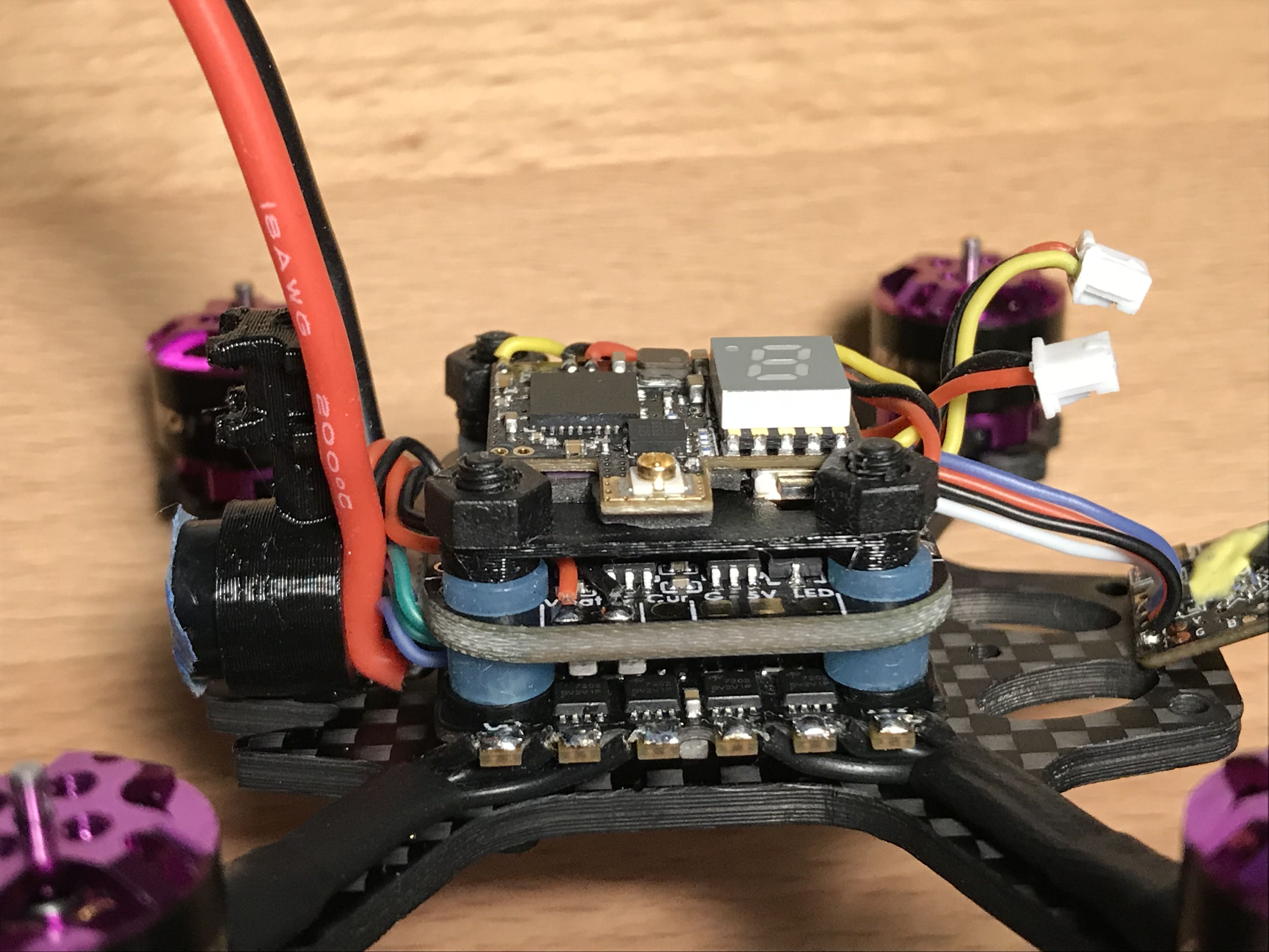
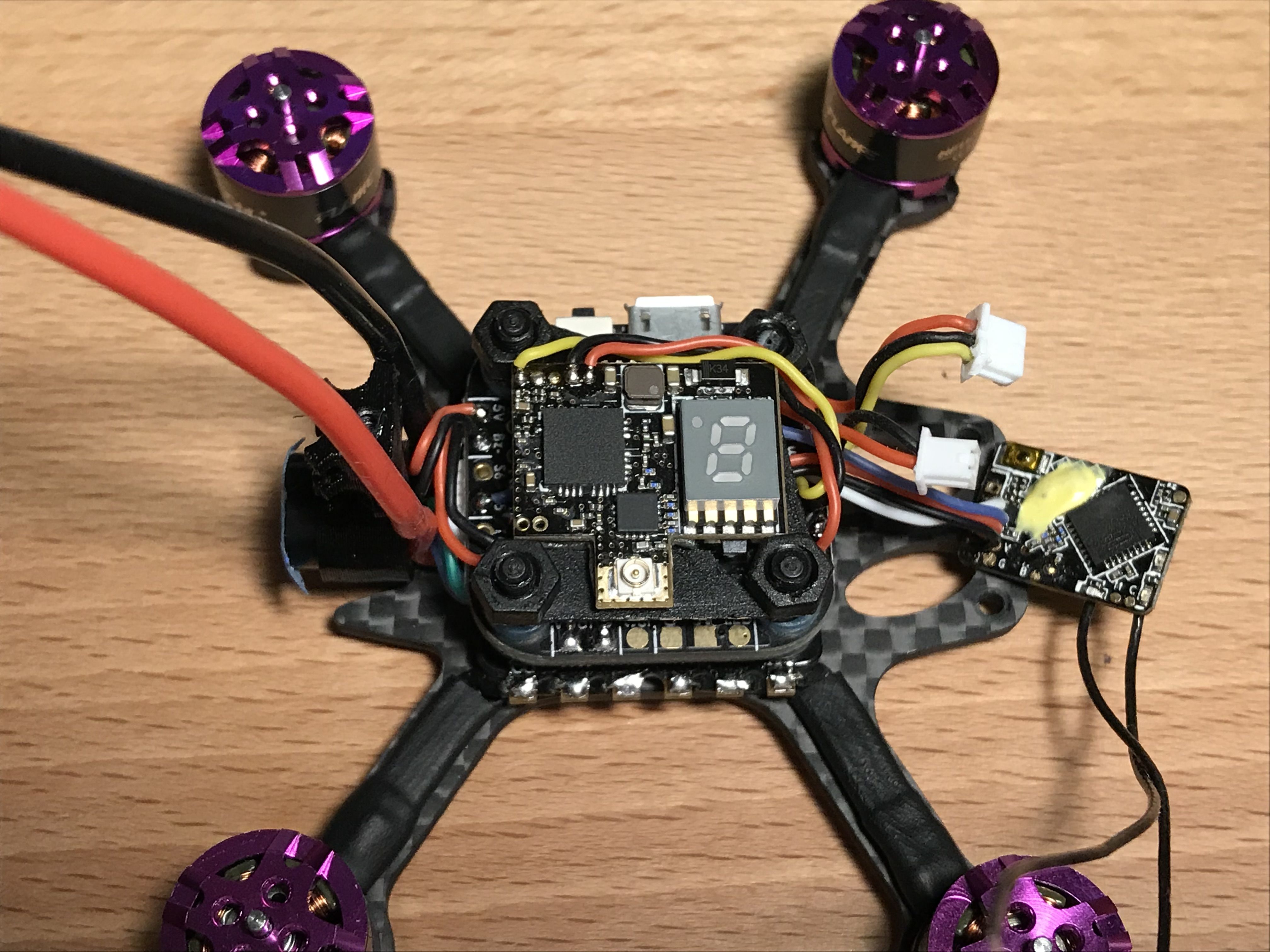
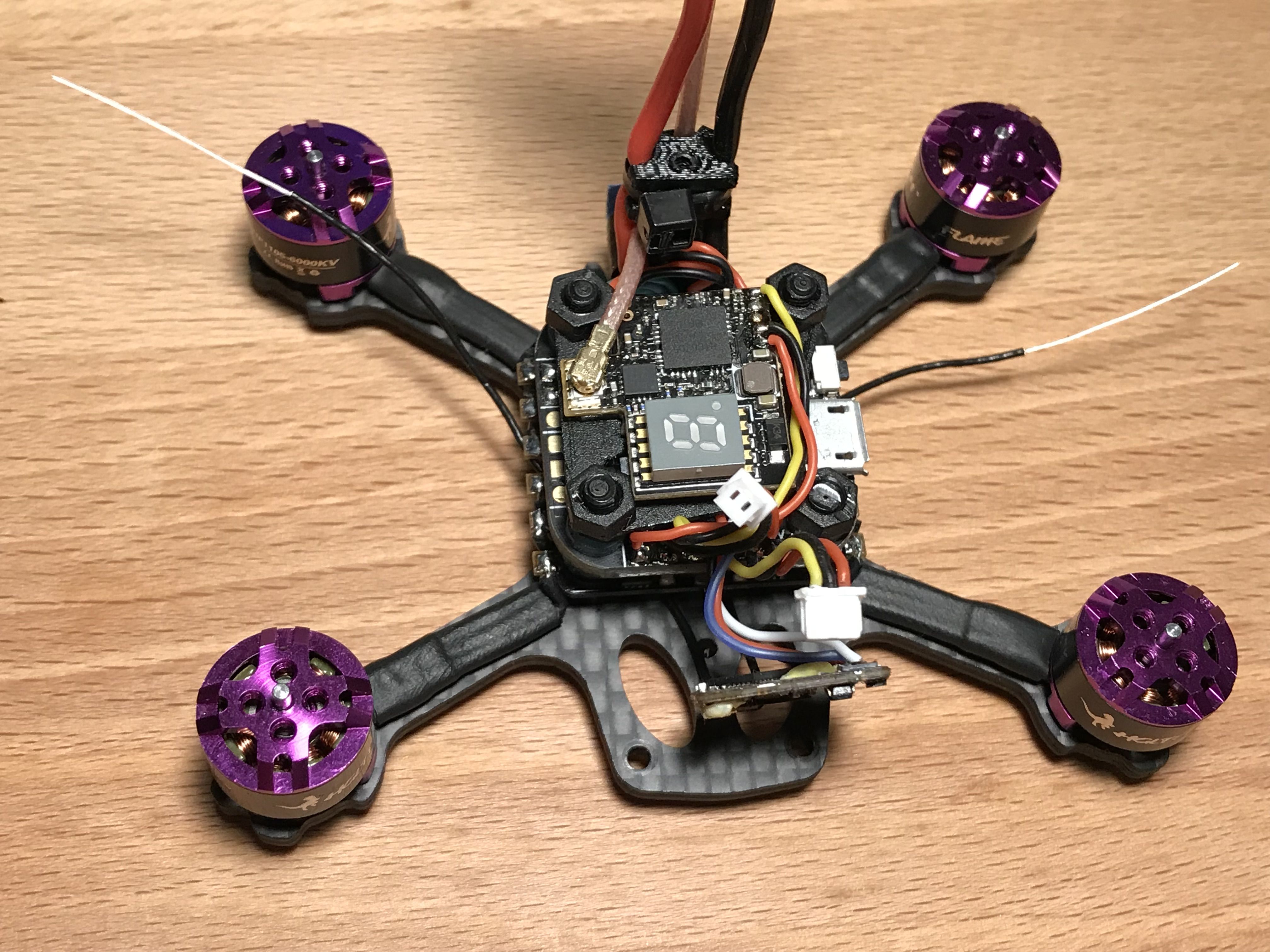
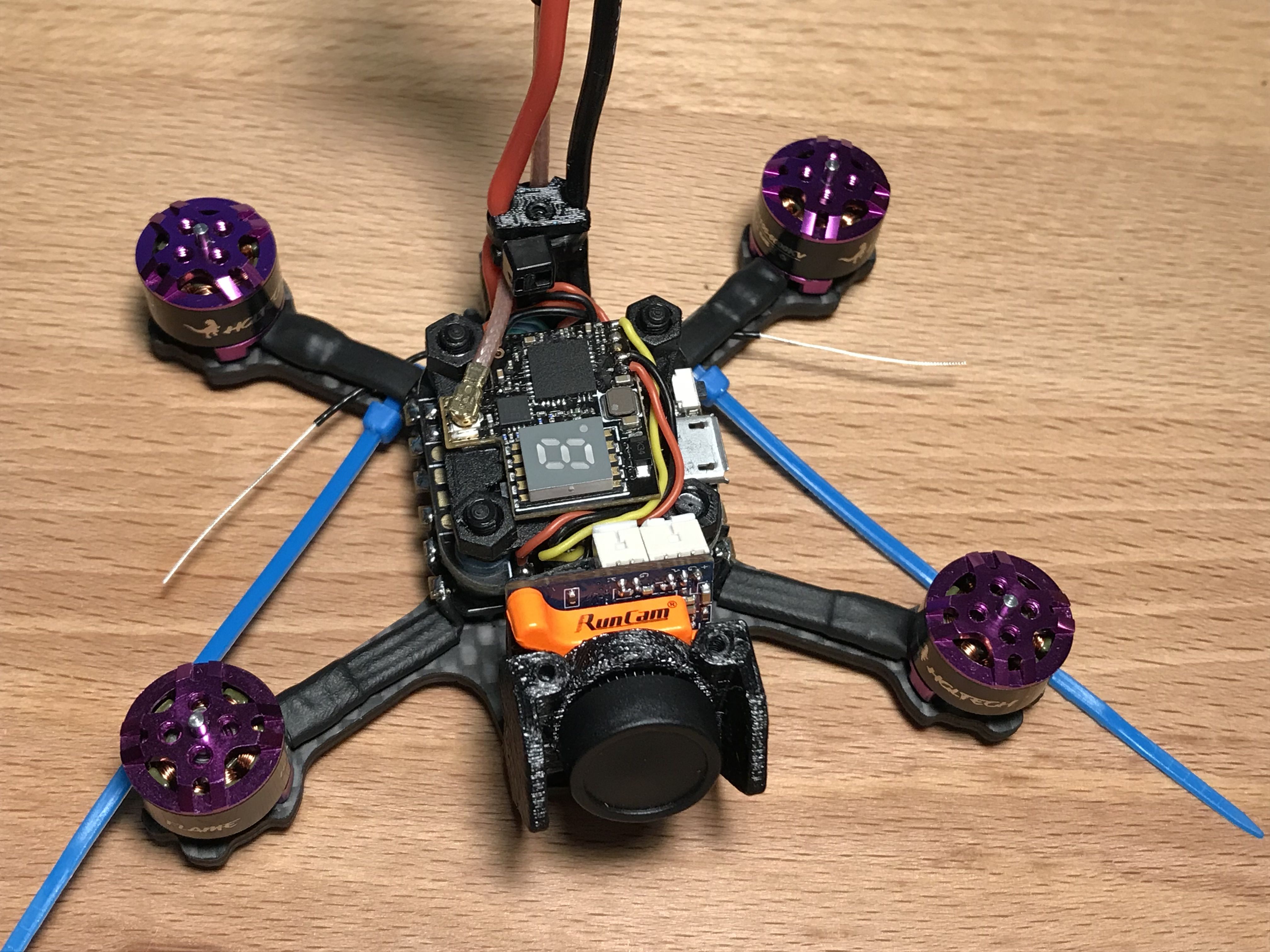
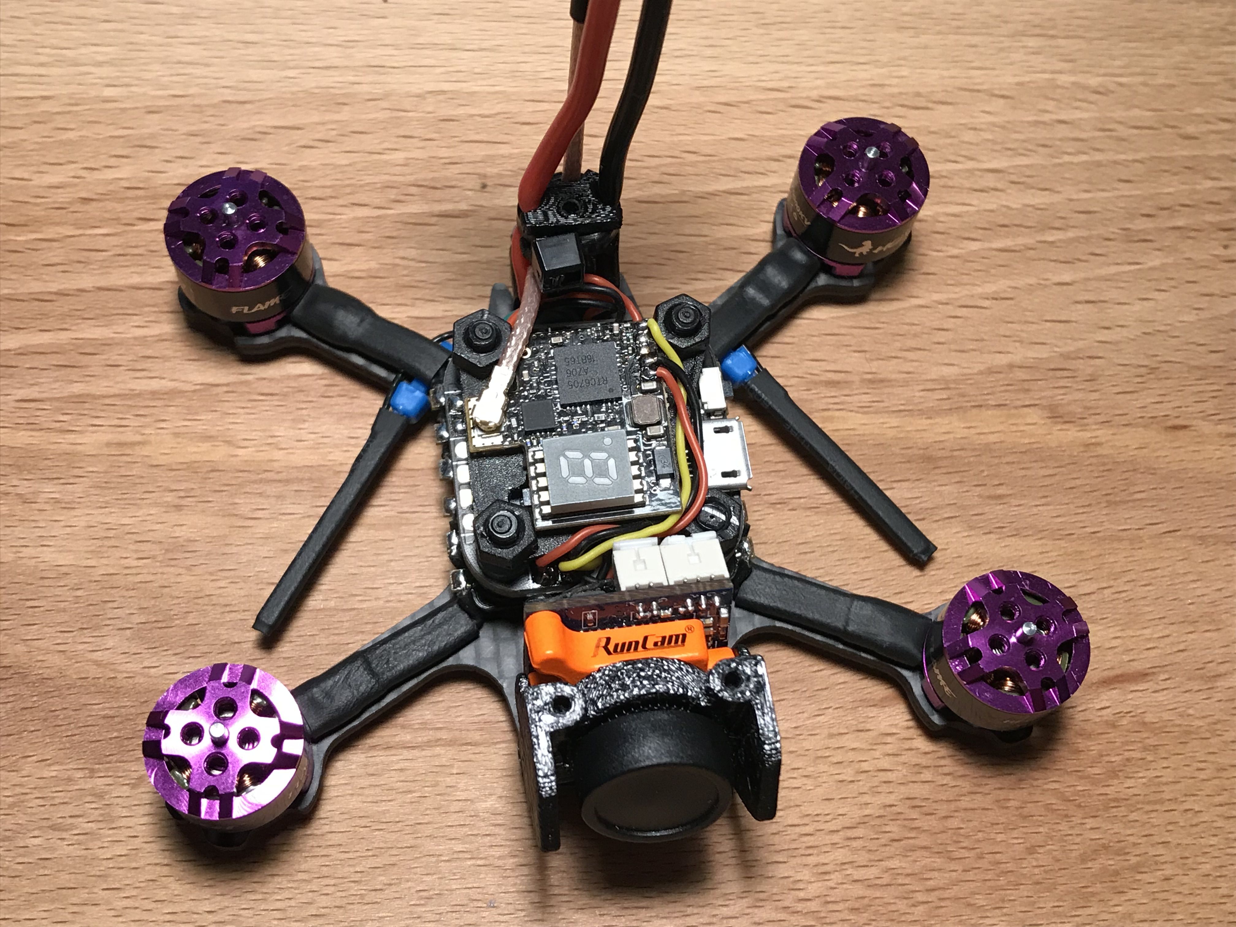
Done With the Wiring
Congratulations! That was the most challenging part. This is how the end result should look like:
Now it's time to check the soldering with a multimeter:
- There should be continuity between all the ground connections on each component.
- There should be no continuity between any 5V pad and any ground pad.
- There should be no continuity between Vbat and any other pad on the flight controller.
- There should be no continuity between ESC signal pads.
Installing the Flight Controller
Undo the camera pod screws and put the pod aside.
Cut four 1 mm nylon washers as shown and put them on top of the ESC.
Put the flight controller on top, connect the ESC plug and carefully route the signal wires so they are not jammed between the flight controller and the ESC connector.
Installing the Rear Standoff with the Buzzer
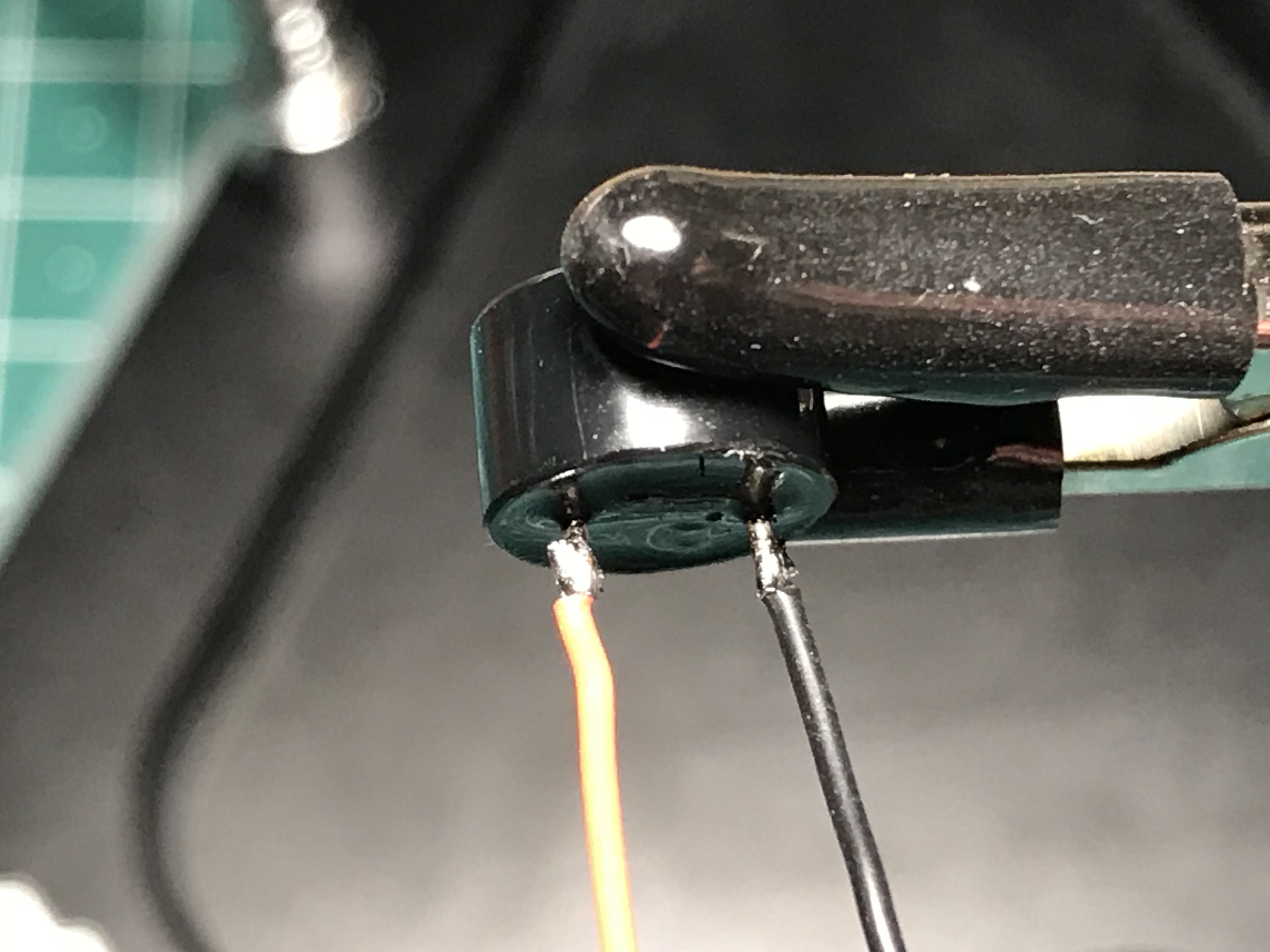
Shorten the buzzer pins and solder some 3 cm of wire on. Make sure to solder the wires to the outside of the buzzer's legs as demonstrated.
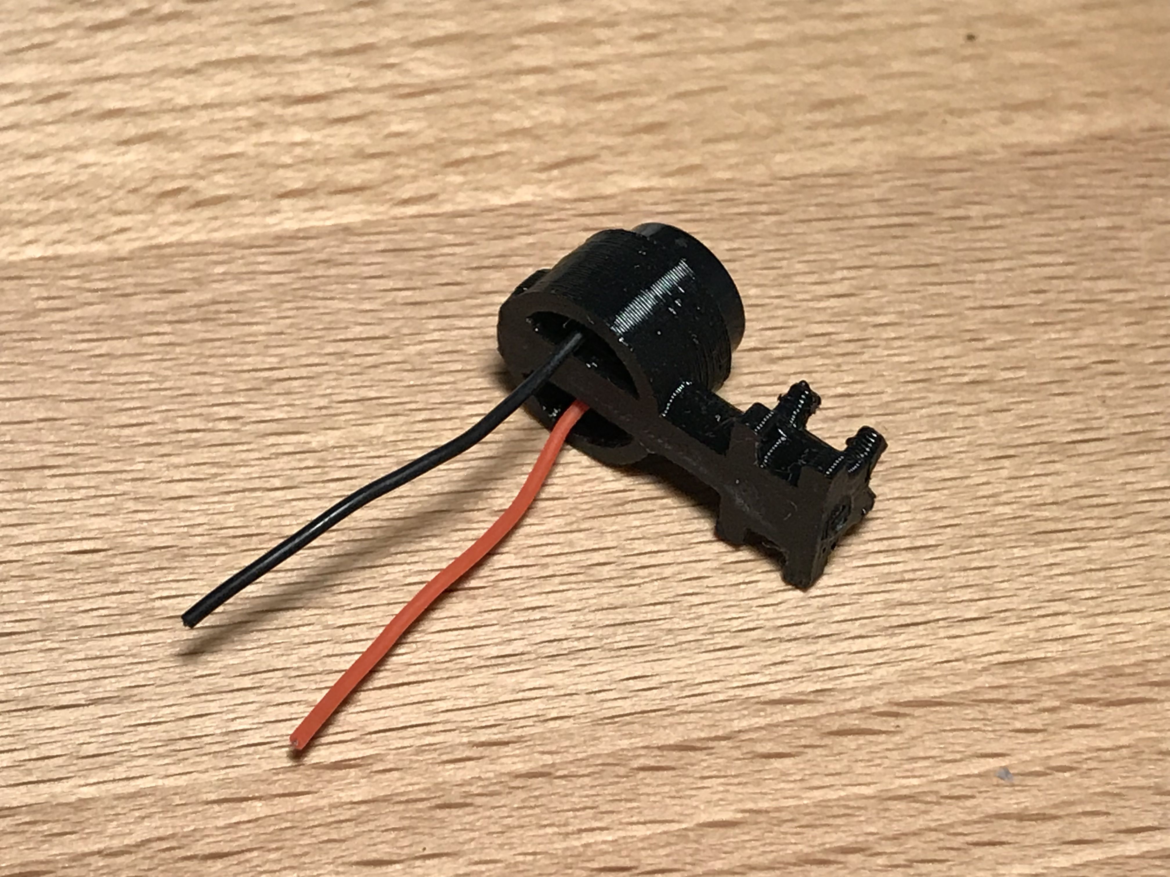
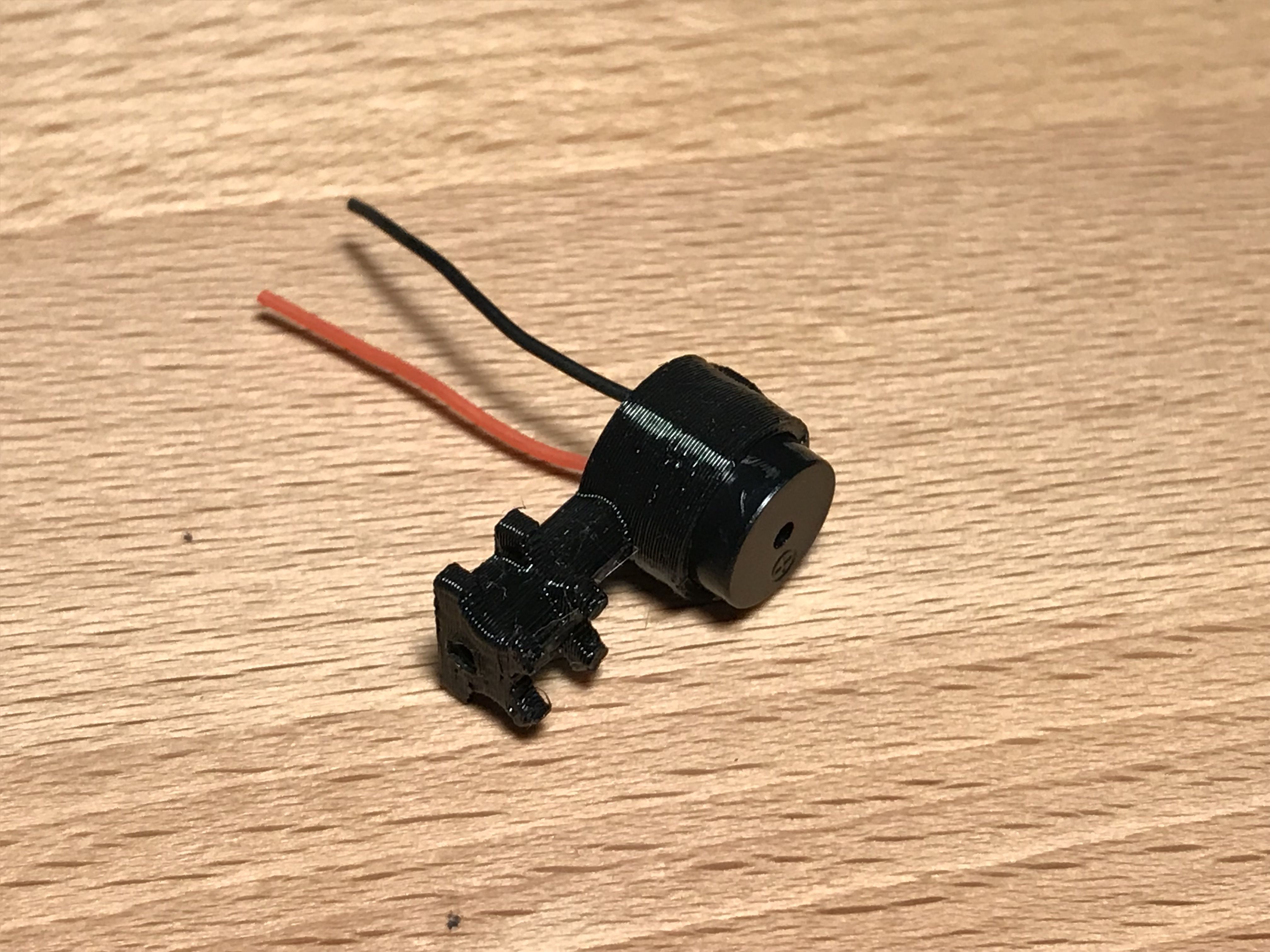
Squeeze the buzzer into the rear standoff. It is a very tight fit so the buzzer is held in place by friction.
Screw the rear standoff in place with a 7 mm M2 steel screw, cut the buzer wires to length and solder them to the flight controller.
- "+" on the buzzer to 5V on the flight controller.
- "-" on the busser to Buz- on the flight controller
Installing the VTX
Put the VTX plate on top of the flight controller and use M3 nylon nuts to fix it in place. Do not tighten the nuts too strong so the flight controller's soft mounting grommets are not squeezed too much.
Trim the screw that is not holding the VTX plate.
Put some double-sided sticky foam at the bottom of the VTX and attach it to the plate. Make sure the button fits into the cut-out in the plate.
Installing the Antenna
Route the antenna wire between the power leads from the back and clip in on the VTX.
Use a 2.5 mm zip tie to attach the main leads and the antenna to the rear standoff as shown. The standoff has notches for the wires and the zip tie at the top.
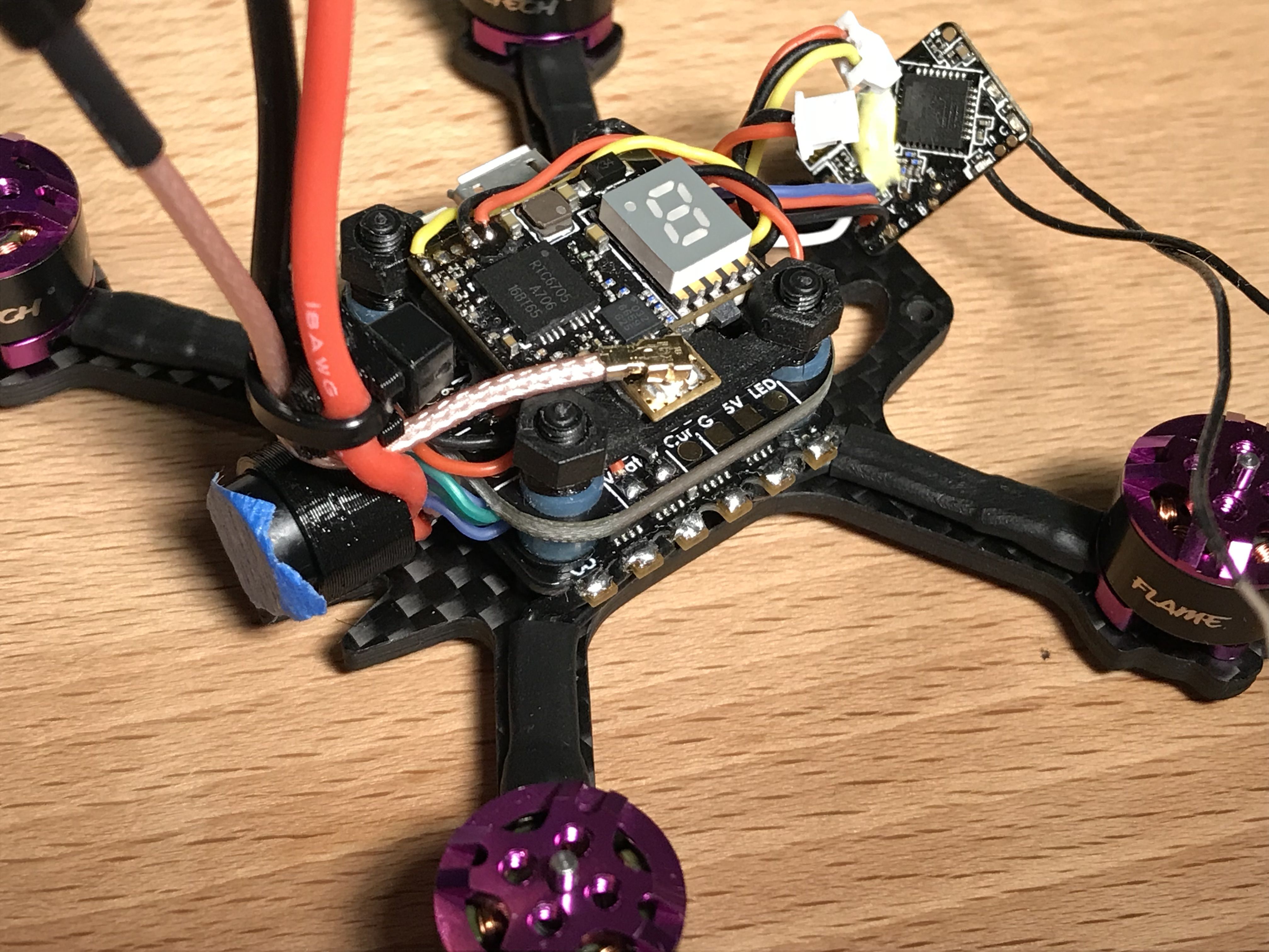
Installing the Camera
Route the receiver antennas under the ESC.
Use a thin double-sided sticky foam pad to attach the receiver to the back of the camera (warning, perfectionist hazard).
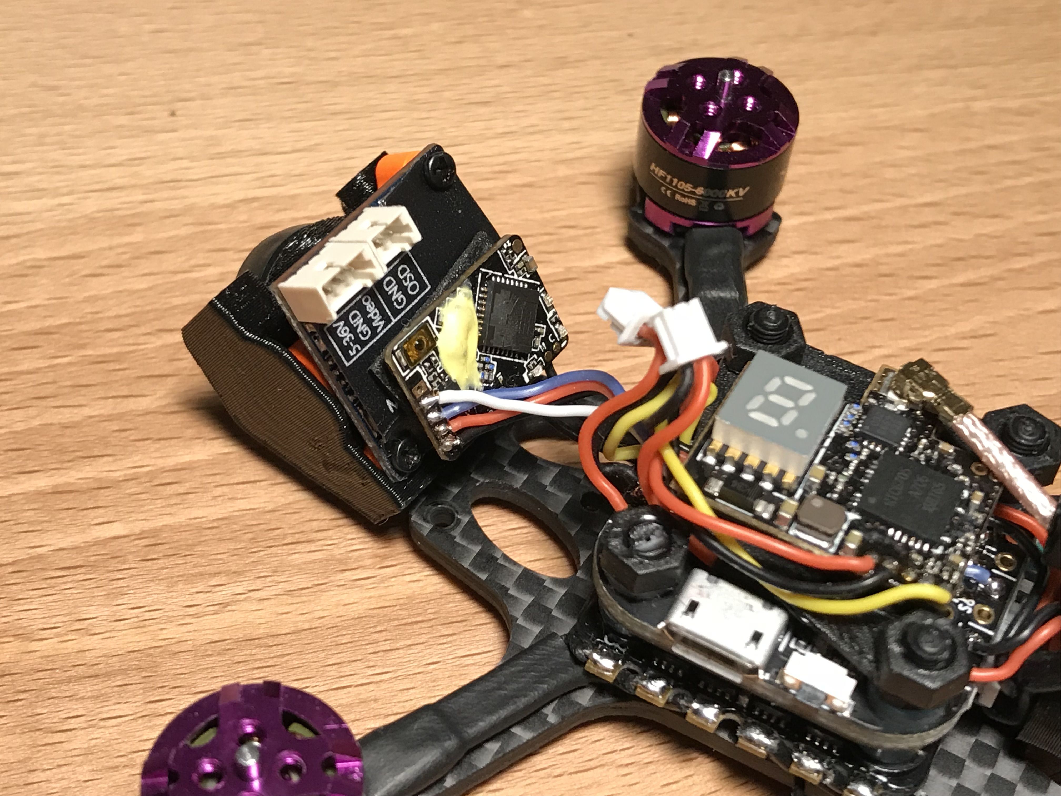
Screw the camera pod to the frame with 5 mm M2 steel screws.
Make sure the wires are not caught between the flight controller, the camera and the receiver so the flight controller is isolated from the vibrations of the frame.
UPDATE: later I discovered that having the video wire (the yellow one coming from the camera) too close to the receiver causes flickering in the video as seen at this animation. The solution is pretty simple: route the wire so it is a bit further away from the receiver's components (two millimeter difference made the problem go away completely).
Mounting the Receiver Antennas
Attach two thin zip ties to the back arms as shown (I'm out of thin black zip ties T_T).
Route the antennas to the back and under the motor wires.
Cut the appropriate length of heatshrink tube and shrink the antennas to the zip ties.
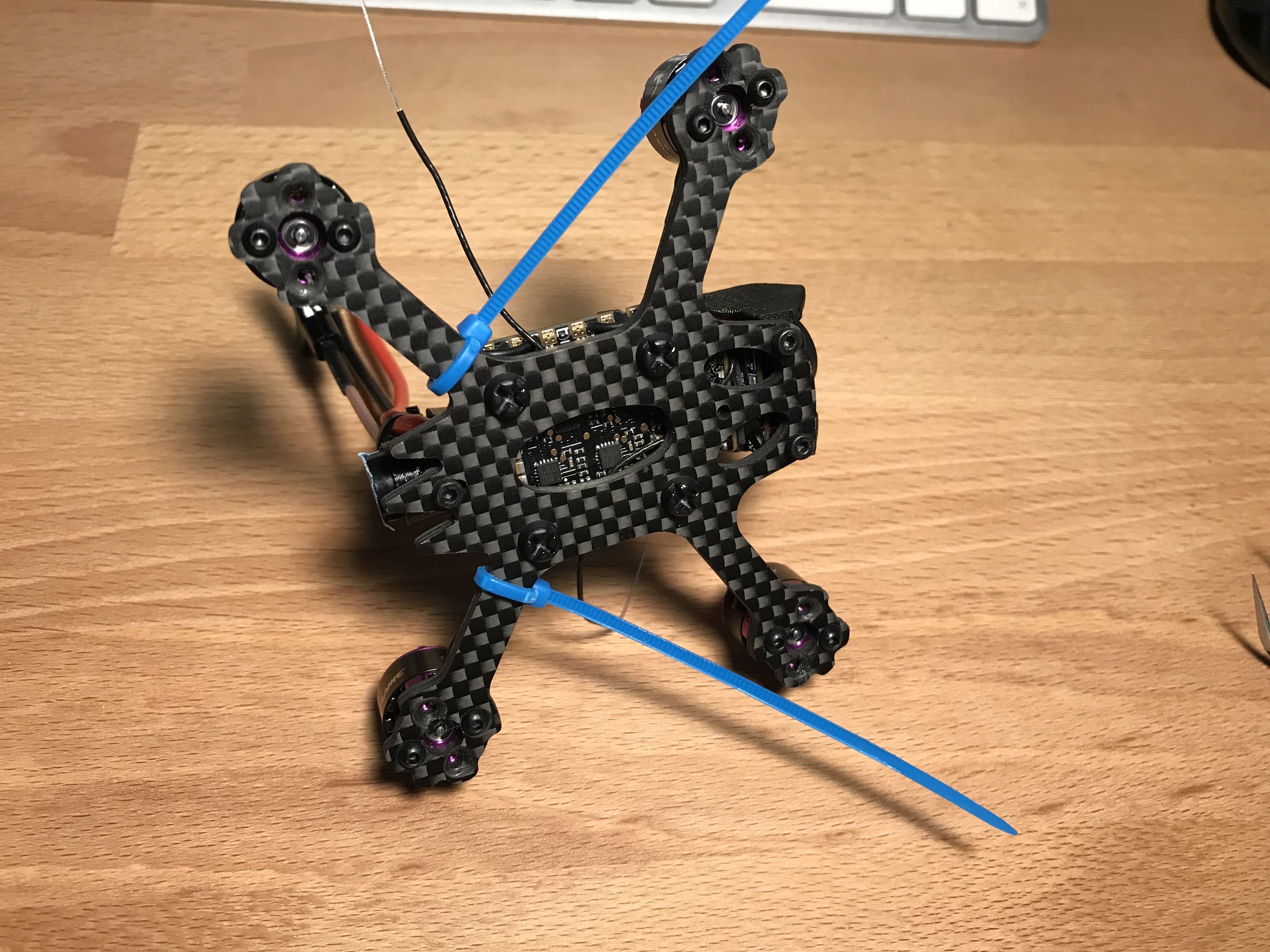
Mounting the Top Plate
Cut a piece of a 2 mm silicone battery mat, press the top plate hard against it so the contour is visible afterwards and cut out the portions that are not needed.
Stick the pad to the top plate.
Use M2 steel screws to attach the top plate. I used 5 mm screws at the front and a 7 mm at the back.
Soldering the Main Leads Connector
Strap the battery to the top plate so the center of gravity is at the middle of the flight controller when you look from the top.
Measure how long the power leads should be, cut them to length and solder the connector on.
I also had to solder XT30 connectors to the batteries since they were shipped with JST RCY.
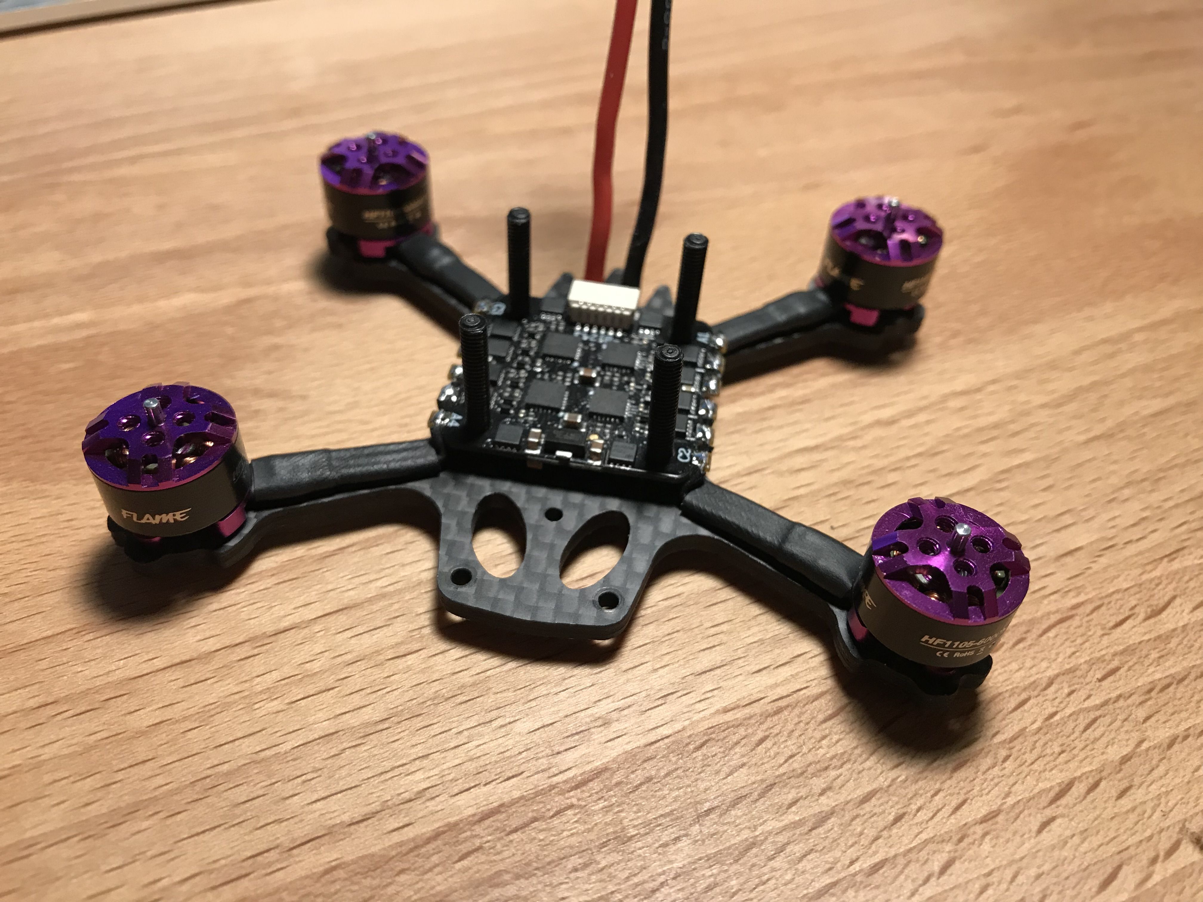
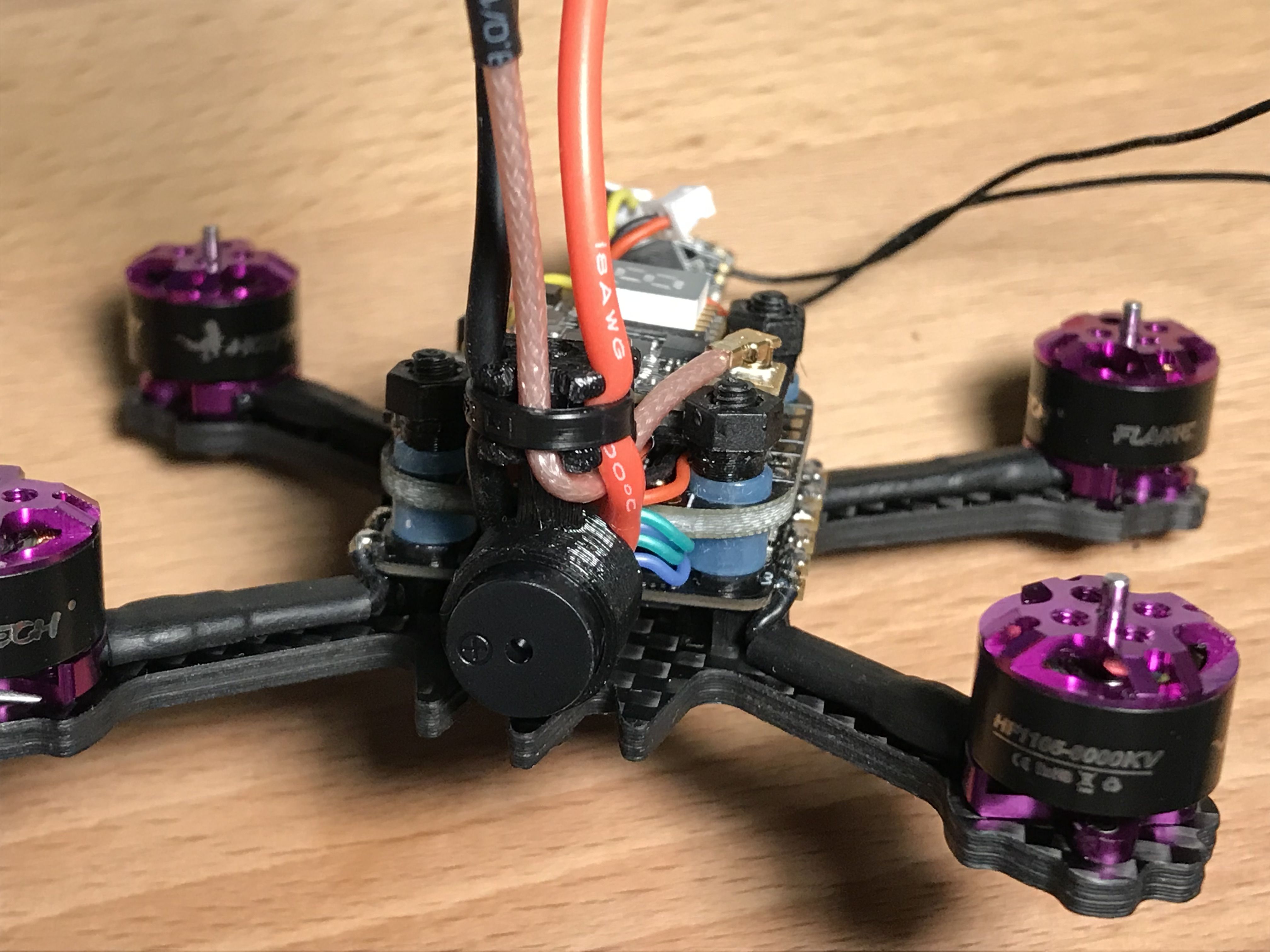
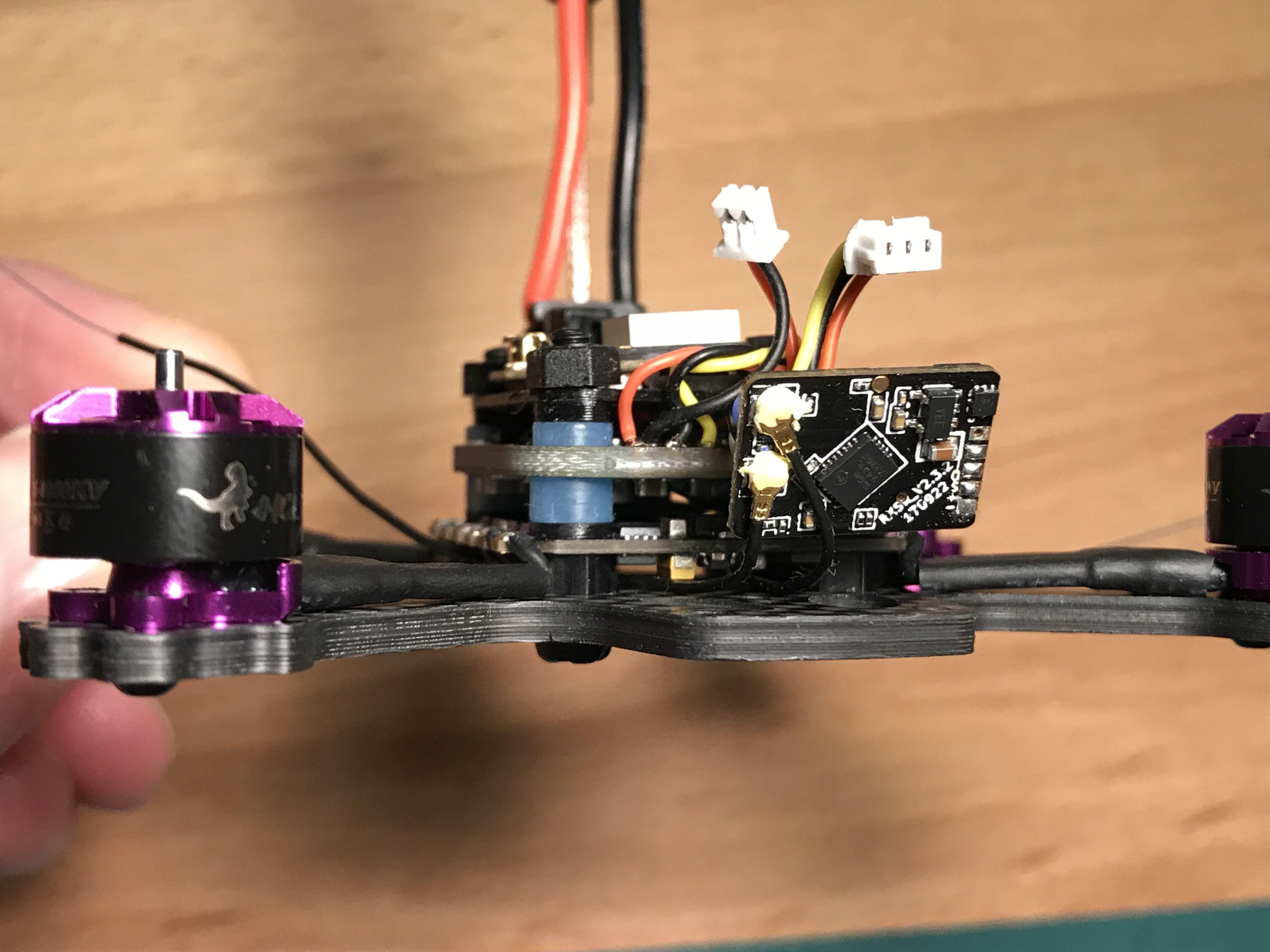
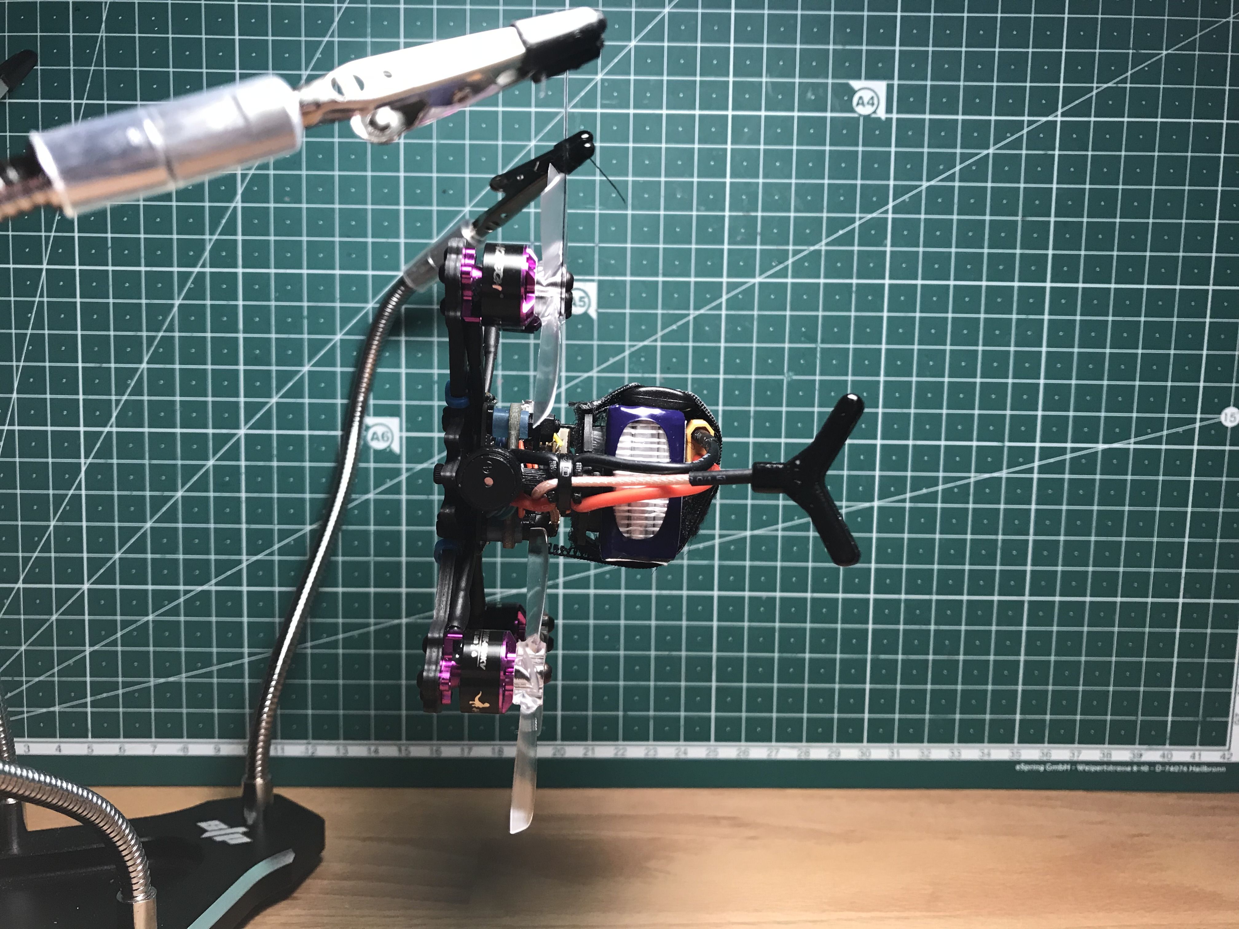
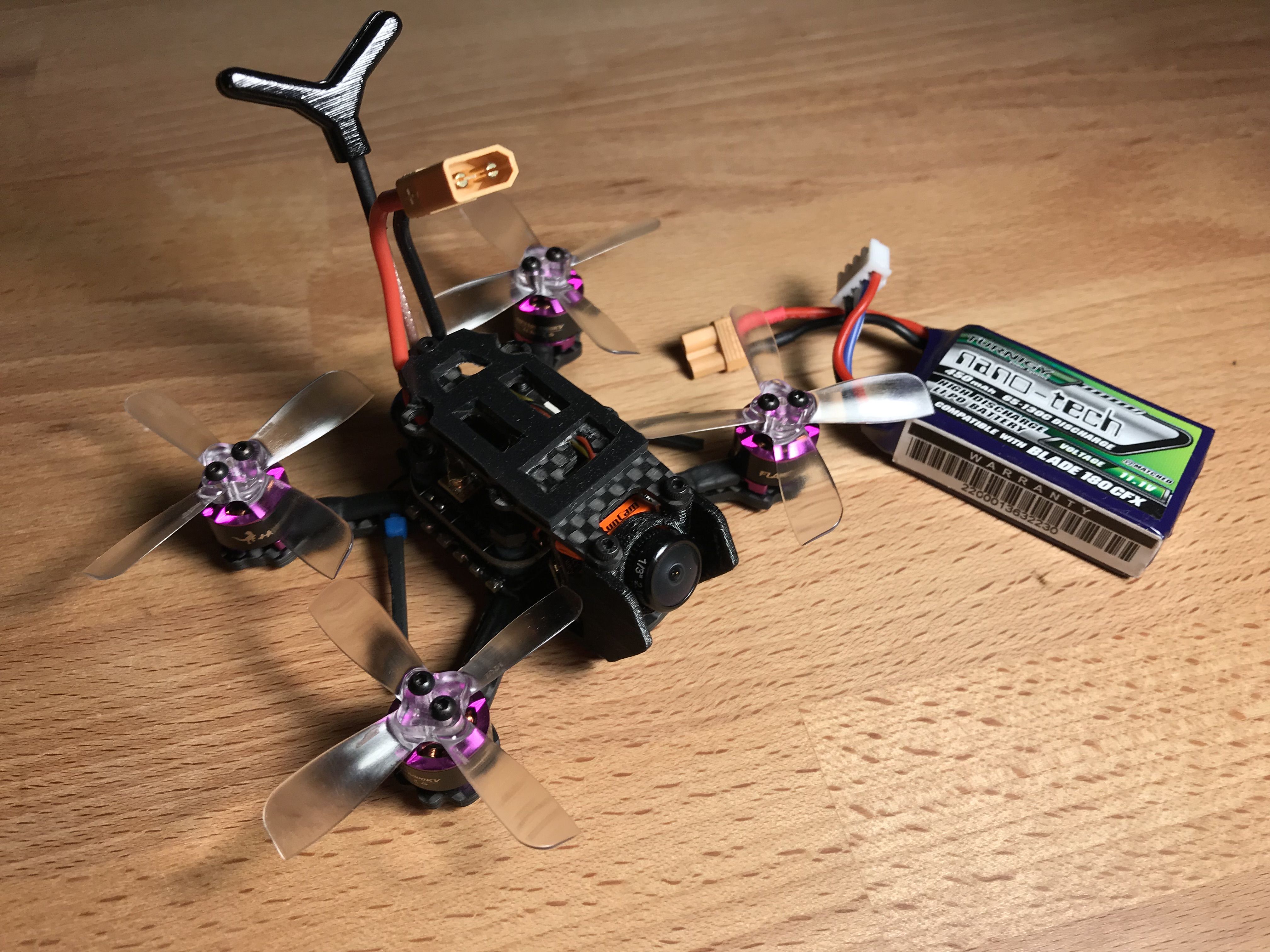
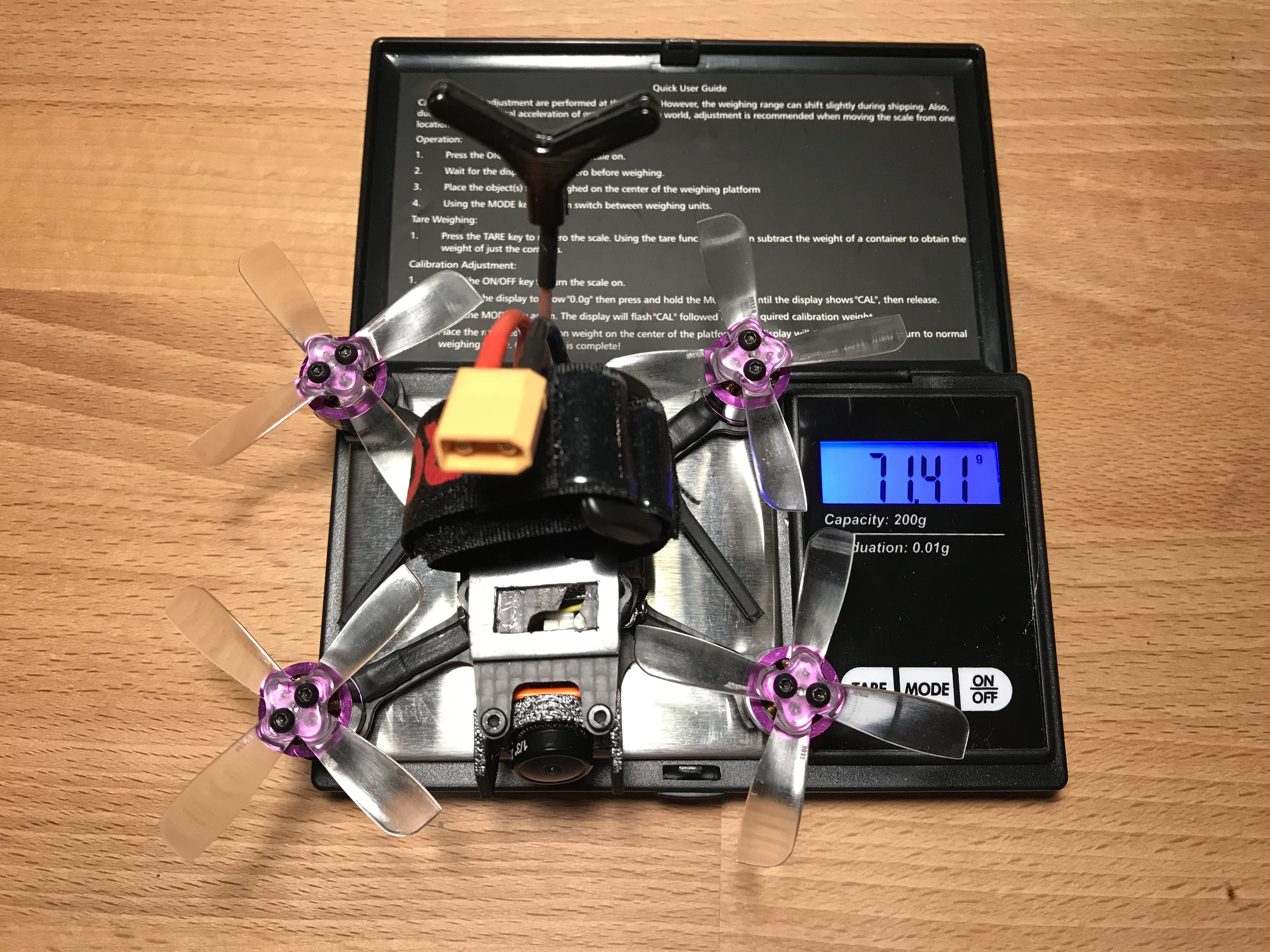
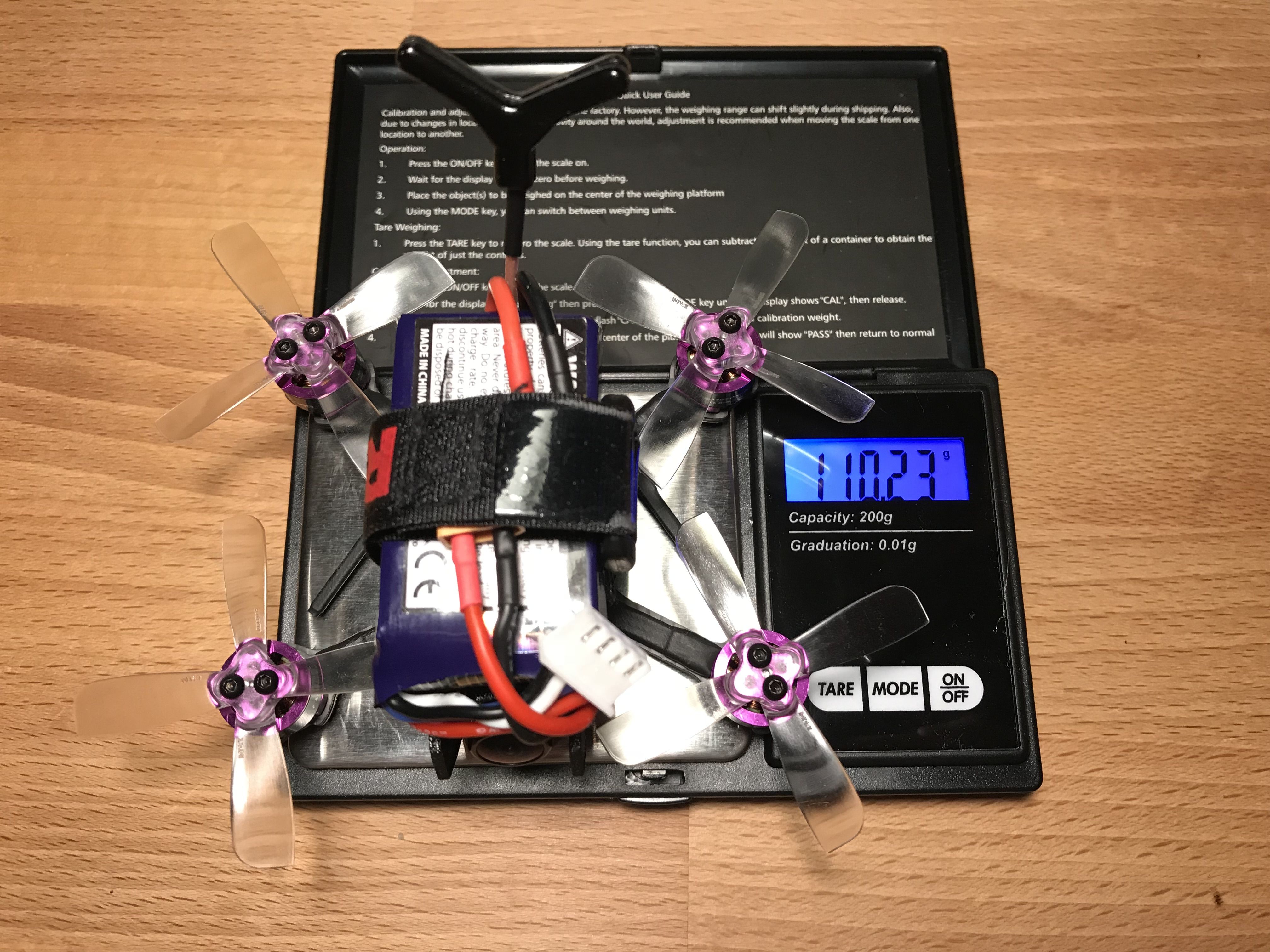
Oh She Looks so Top-Heavy with That Battery
As you can see at the picture below, the center of gravity is just a tiny bit above the propeller line.
She looks super top-heavy, but she's actually not.
Betaflight Configuration
This build requires some custom configuration on top of the regular stuff.
FPV Camera Control
Camera control resource needs to be assigned to the RSSI pad the OSD pin resistor is soldered to.
resource CAMERA_CONTROL 1 A00
save
FrSky Smart Port Telemetry
Matek F411 requires soft serial to be configured on the S5 pad the Smart Port wire is soldered to in order to work with inverted signal.
feature SOFTSERIAL
resource MOTOR 5 NONE
resource SERIAL_TX 11 B03
save
Select "SmartPort" telemetry output for SOFTSERIAL1 at the Ports tab in Betaflight Configurator.
Custom Motor Mix
The frame has a dead cat configuration, so I came up with a custom motor mix to address front to back asymmetrical motor placement.
It's still to be tested if the mix provides any benefits, but here you have it anyway.
mixer CUSTOM
mmix 0  1.000 -0.893  0.704 -1.000
mmix 1  1.000 -1.000 -0.704  1.000
mmix 2  1.000  0.893  0.704  1.000
mmix 3  1.000  1.000 -0.704 -1.000
save
Is There Flight Footage Anywhere?
Yes! Here is the footage and my thoughts on the build after having some forty packs through.
Thank You for Your Attention
Thank you for making it this far. I hope you liked it.
Here are more pictures to look at.
Photos


Part List
Show stores (5)
Hi nice build. will runcam swift micro fit on this frame? is there any cam side plate in the frame. How do we fit in a cam?

Hey, thanks! The frame does not have any camera mounting solution. A nano-size camera can be fitted between the front standoffs and fixed with a rubber band or something like that. Micro sized cameras are too big for that, so I had to design and 3d-print a mount / standoff thing. You can find it here https://www.thingiverse.com/thing:2774645
I used the Micro Sparrow. If your version of swift micro looks like the one on the picture, it should fit into the printed mount https://rotorbuilds.com/pictures/f_6262_ct1ftUX3XCO8ySXix98yobwhZ.jpg
Speaking of cmos 600tvm cam, if the lens is small enough to fit between the standoffs, I think rubber bands should work too.


Truly a perfect build log.
Thanks for putting so much effort into this! I'll be emulating this quite accurately.


Hi i follow all the steps and all working fine expect , when it flys after few seconds motors stop working .. than again and again
Looks like a faulty ESC to me. Theoretically something could also be wrong with the motor channel on the flight controller, so to be 100% shure you can try swapping the motor signal wires in the connector that goes to the ESC. The connector has tiny plastic tabs that hold the female plugs inside the housing so if you bend the tabs slightly outwards you can pull the wire out. Be careful, the tabs are pretty easy to break. Try swapping the working and the problematic motor wires and see if the problem stil persists. If it is the same motor not working properly, the ESC is not good. If the problem follows the wire, then the flight controller is not good.


Thanks for the great build log, the zoomed in pics are great. I've been debating between this FC and the Omnibus F4 you mentioned, your write up helped me decide, thank you.


Awesome build log! I guess we won't be getting a Runcam Split Micro on one of these things considering how tight this build is.
Thank you!
Well, that could be achieved in theory by reverting to an underslung battery and redesigning standoffs to make the quad ridiculously tall (it's 22 mm now and Split Mini needs 12 mm extra) while increasing the weight by 15 grams, and that's like 13% more. Taller 3D-printed standoff and camera pod will be more fragile. I'm also not sure how well it will fly with such mass distribution.
Overall I don't think that would be good for what I built this thing for – outdoor freestyle bashing ;)


Thats alot of efforts. I am facing a unique problem. I have a 16 x 16 FC and a 20 x 20 caddx turtle v2 which i would like to mount on this frame. If i mount the caddx then how do i mount the 16 x 16 fc. I want to move all the parts of my iflight cinebee 75hd to this frame. a little bit confused if u can help it would be great.